Industrial / Door Hardware
Installation Instructions for Sargent 12-FM8700 Surface Vertical Rod Exit Device
Comprehensive installation guide for the Sargent 12-FM8700 Surface Vertical Rod Exit Device. This manual covers door preparation, component installation, rod adjustments, and rail cutting procedures.
Table of contents
Manual images
Click an image to enlargeQuick guide from the manual
This document provides installation instructions for the Sargent 12-FM8700 Surface Vertical Rod Exit Device. Before beginning, ensure you have all necessary tools, including a hacksaw, drill with specific bits, taps, and Allen wrenches. The device is a component of a specific hardware combination required to meet FEMA 361 requirements.
Door preparation
Proper alignment is critical for the installation:
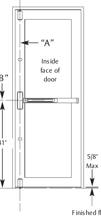
- Mark vertical reference line A, which serves as the centerline for the chassis, top, and bottom cases.
- Mark horizontal reference line B at 41 inches above the finished floor. This is the centerline for the chassis and rail.
- Use the provided templates for the top case and chassis to mark mounting locations on the door.
Installation steps
Follow these steps in the specified sequence:
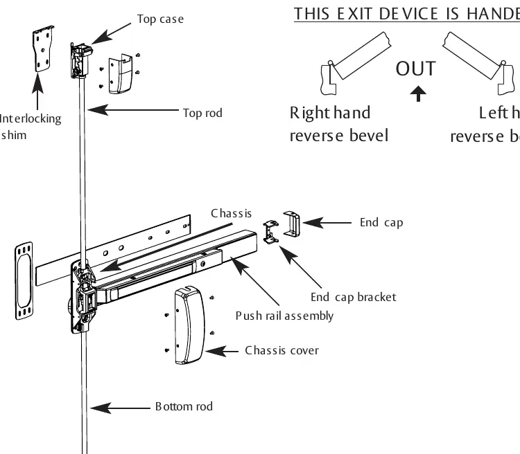
- Top Bolt and Strike: Prepare the frame cut-out, install the 659 Top Bolt/Strike, and align the interlocking shim with the door closed.
- Top Case: Center the Top Chassis Assembly and Interlocking Shim on the vertical reference line. Drill mounting holes and secure with the provided socket head screws.
- Center Chassis: Secure the chassis and chassis shim using the four corner mounting holes.
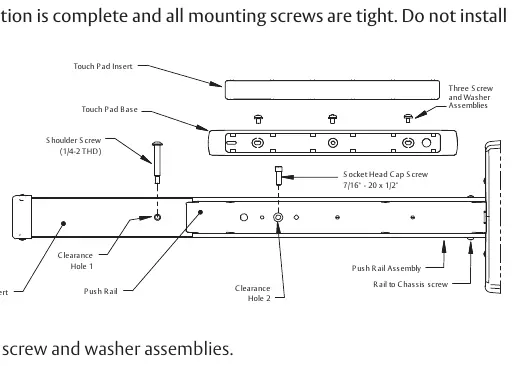
- Rail Installation: Level the rail assembly on the door, mark locations, drill and tap holes, and install the push rail assembly.
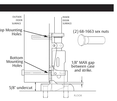
- Bottom Strike: Transfer the vertical centerline to the threshold, drill holes for sleeve anchors, and secure the strike.
- Bottom Case: Align the bottom case for a 1/8-inch maximum gap between the case and the strike. Drill and tap mounting holes.
- Rods: Slide the top and bottom rods into the main slide and center chassis. Thread them into their respective cases until finger-tight and secure with adjustment pins.
Adjustments and cutting
Rod Adjustment: Rough adjustments are made by changing the hole used for the adjustment pin. Fine adjustments are made by turning the rod into the case to shorten it or out of the case to lengthen it. The top bolt must be in the hold-back position before the door opens.
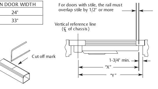
Rail Cutting: Determine the rail length dimension 'X' by subtracting 1-3/4 inches from dimension 'Y'. Ensure the cut is straight and remove sharp edges with a file.
Fire-rated requirements
For all 12-FM8700 single door applications, four thermal pins are required. Refer to Template 4628 for specific drilling and installation details.
Practical help
Common problems
Top bolt not in hold-back position
Ensure the top bolt is in the hold-back position before the door opens. If not, extend the top bolt.
Bottom bolt clearance issues
The bottom bolt must clear the bottom strike by at least 1/8 inch throughout the swing of the door.
Rail length incorrect
Determine length 'X' by subtracting 1-3/4 inches from dimension 'Y'. Ensure the cut is straight.
Before use
- Verify all required tools are available (hacksaw, drill, taps, Allen wrenches).
- Mark vertical reference line A (centerline for cases).
- Mark horizontal reference line B at 41 inches above the finished floor.
- Ensure the door is closed when aligning the interlocking shim.
- Check for FEMA 361 compliance requirements if applicable.
Specs in practice
- Reference Line A
- Vertical centerline for chassis, top, and bottom cases.
- Reference Line B
- Horizontal centerline for chassis and rail, 41 inches above finished floor.
- Rough Adjustment
- Changing the hole used for the adjustment pin.
- Fine Adjustment
- Turning the rod into or out of the top/bottom cases.
Images and diagrams
- Exploded view of the exit device showing top/bottom rods, cases, and chassis.
- Door preparation diagram showing reference lines A and B.
- Rail cutting diagram showing 'X' and 'Y' dimensions.
Model compatibility
- Device is a component for FEMA 361 requirements.
- Single door applications require (4) thermal pins (see Template 4628).

Manual page author
David Miller
Documentation analyst
Organizes user manual content into clear summaries, with attention to model details, product context, and everyday usability.