Industrial / Pressure Sensors
User Manual for Sauermann Si-CA 230 Gas Analyzer
Comprehensive user guide for the Sauermann Si-CA 230 gas analyzer. Includes setup, flue gas analysis procedures, maintenance, sensor replacement, and technical specifications.
Quick answers from the manual
Quick answer
- The Sauermann Si-CA 230 is a flue gas analyzer for emissions monitoring. It features a color touch screen, interchangeable sensors, and supports various measurements like gas analysis, draft, and CO monitoring. p. 4, 6
Key actions
- Perform flue gas analysis p. 13
First start
- Initial setup p. 10
Show 2 more answers Show less
Technical specifications
| Parameter | Value | Meaning | Pages |
|---|---|---|---|
| Battery | 5100 mAh | Rechargeable Li-Ion battery, >8h life. | p. 11 |
| Operating Temperature | -5 to 45 °C | Environmental conditions of use. | p. 11 |
| CO Measurement | 0 to 50,000 ppm | With dilution enabled. | p. 12 |
Where to find it in the PDF
- Safety Instructions p. 5
- First Start-up p. 10
Table of contents
Manual images
Click an image to enlargeQuick Guide
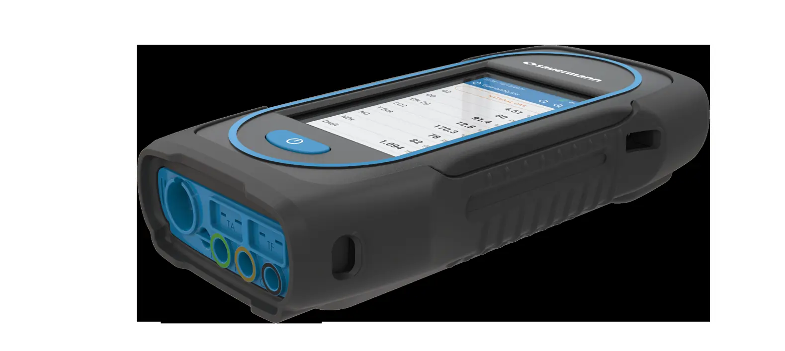
The Sauermann Si-CA 230 is a professional flue gas analyzer designed for HVACR and combustion emissions monitoring. Before first use, ensure the battery is fully charged for 12 hours. During operation, the analyzer must be kept in a vertical position to ensure the water trap functions correctly. Always perform the autozero cycle with the probe outside of the stack.
Safety Instructions
Important Warnings:
- The device is for professional use by trained experts only.
- Do not expose the probe tip to open flames.
- The device must be kept in a vertical position during operation.
- Condensate is acidic; do not touch it directly and ensure it does not leak into the device.
- Keep a distance of at least 10 cm from pacemakers.
- Do not use in explosive or corrosive environments or ATEX zones.
- If the device is damaged or operates abnormally, contact Sauermann After-sales service.
First Start-up
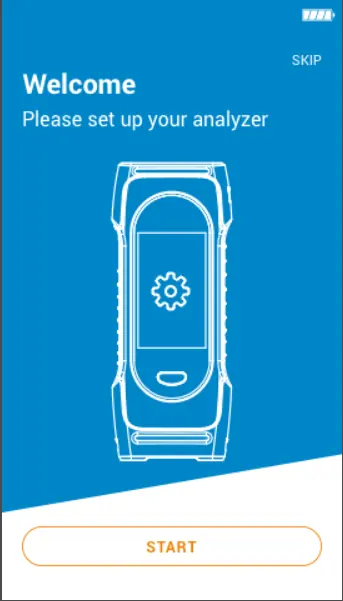
Upon turning on the device (press and hold for 3 seconds), follow the on-screen configuration wizard:
- Select your country and language.
- Set the date and time format.
- Configure time zone.
- Select pump status after autozero.
- Wait for the autozero process to complete with the probe outside the chimney.
Performing Flue Gas Analysis
To perform an analysis:
- Connect the flue gas probe to the analyzer.
- Turn on the instrument and wait for the autozero cycle.
- Insert the probe into the flue/stack.
- Tap the Menu icon and select "Gas analysis".
- Select the fuel type from the list.
- Perform the measurement for at least 3 minutes until values stabilize.
You can also perform draft measurements, CO monitoring, and gas tightness tests via the "Other Measurements" menu.
Maintenance
Sensor Replacement:
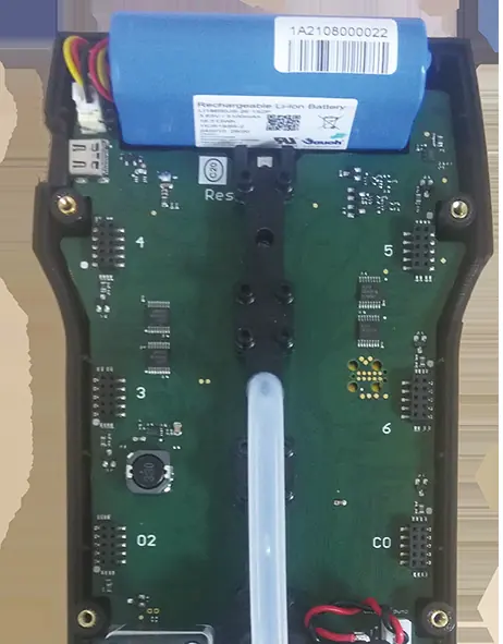
- Turn off the analyzer and remove the rubber holster.
- Open the back shell by removing the 6 screws.
- Pull the used sensor off the manifold and replace it with a new one, ensuring correct alignment with the pins.
- Wait for the sensor to stabilize (polarization time varies by sensor type).
Filter Replacement:
- Disconnect the smoke probe.
- Detach the lower part of the water trap by turning it left.
- Replace the internal filter and reassemble.
Cleaning: Clean the housing with a damp cloth using distilled water. Do not use isopropanol.
Technical Specifications
The analyzer features a 4.3" color touch screen, 2000 points of memory, and wireless connectivity. It supports various interchangeable electrochemical sensors for O2, CO, NO, NO2, SO2, H2S, and CxHy. The battery provides over 8 hours of operation with a 6.5-hour full charge time.
Manufacturer information
Sauermann
Practical help
Common problems
Sensor error message after replacement
It is normal for a newly installed sensor to show 'Current Error'. Wait for the designated stabilization time (e.g., 1 hour for O2, 12 hours for NO).
Insufficient memory
The analyzer has a limit of 2000 points. If memory is full, change the data logging settings (time interval or duration).
Condensate leaking into device
Ensure the water trap is always in a vertical position during operation and empty it before storing.
Before use
- Charge battery for 12 hours before first use
- Ensure water trap is vertical
- Perform autozero with probe out of stack
- Check probe connections (hoses and thermocouple)
- Verify fuel selection matches the application
Show more Show less
Images and diagrams
- Probe connection: Connect hoses to G (gas) and P+ (pressure) ports.
- Water trap: Must be vertical; lower chamber collects condensate, upper chamber holds the filter.
- Sensor location: Specific positions (O2, CO, 3, 4, 5, 6) on the manifold.
Model compatibility
- Not for use as a permanent alarm system.
- Requires trained HVACR experts.
- Compatible with optional probes (CO, CO2, draft, Pitot tubes).

Manual page author
Emily Carter
User documentation editor