HVAC / Condensate Pumps
User Manual for Sauermann LCC-S Configuration Software
Comprehensive user guide for the Sauermann LCC-S configuration software. Learn how to install the software, connect transmitters, configure display, keypad, alarms, relays, and Modbus/Ethernet settings for various transmitter classes.
Quick answers from the manual
Quick answer
- The LCC-S software allows you to configure Sauermann transmitters (Classes 110, 210-R, 310, and monostats), view real-time data, and apply offsets. p. 5
Key actions
- Install software p. 5
- Read transmitter p. 7
- Save configuration p. 28
First start
- Install the software using the provided USB key, then connect your transmitter via the mini-DIN cable to the computer's USB port. p. 5, 7
Show 1 more answers Show less
Maintenance and reset
- Use the 'Bootloader' menu to update the transmitter firmware. p. 27
Table of contents
Manual images
Click an image to enlargeQuick guide from the manual
The LCC-S software is designed to configure Sauermann transmitters (Classes 110, 210-R, 310, and monostats), view real-time data, and apply offsets. To begin, ensure you have a Windows XP, Vista, or 7 system with a USB 2.0 port, 1 GB of RAM, and 1 GB of free disk space.
Software installation
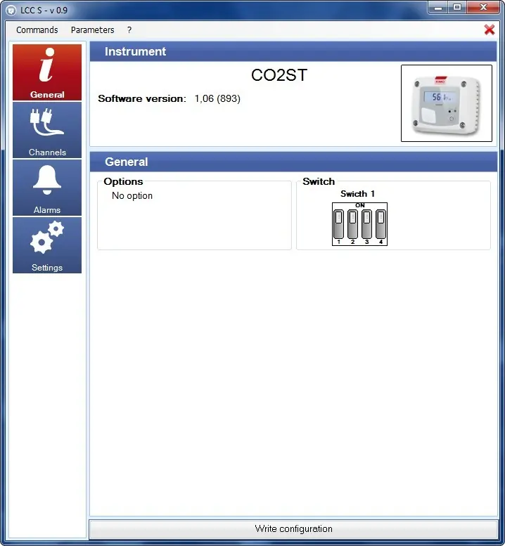
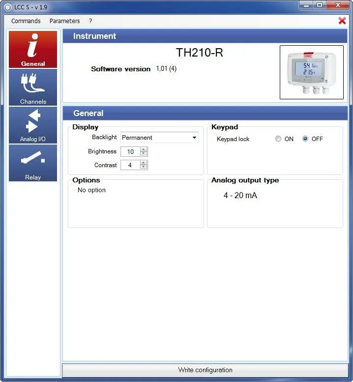
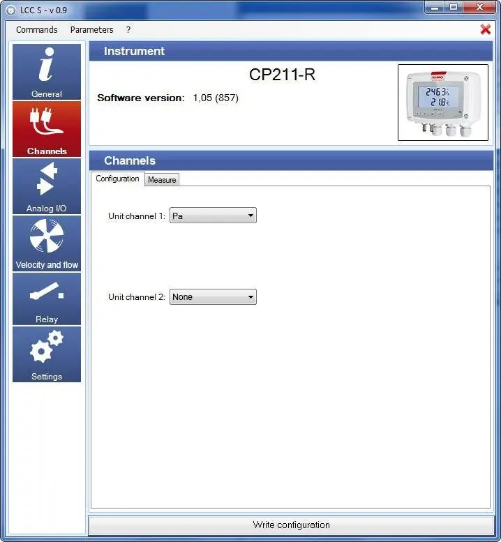
- Insert the provided USB key into your computer's USB port.
- Open the USB key folder and locate the software folder.
- Double-click the .exe file to start the installation.
- Follow the on-screen instructions to complete the setup.
Getting started
Launch the software using the icon on your desktop. The homepage allows you to:
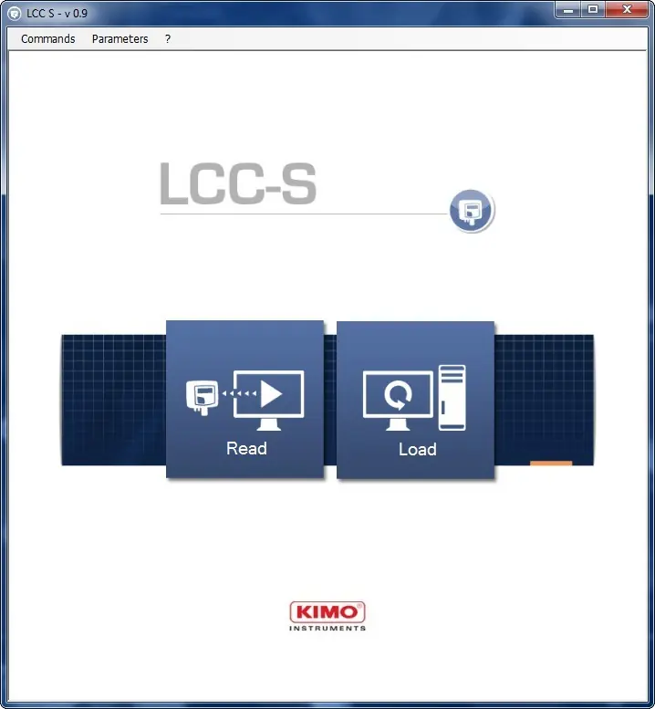
- Read: Retrieve the current configuration from a connected transmitter.
- Load: Recover a previously saved configuration from your computer.
- Menu Bar: Access commands like Write configuration, Save configuration, Correction (offset), and Bootloader (firmware updates).
Reading the transmitter
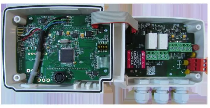
Before reading, ensure the transmitter is powered on and connected via the mini-DIN cable to your computer's USB port. For Class 110 and monostat transmitters, you must set the DIP switches on the electronic board to the "ON" position (to the right) before the software can communicate with the device.
Configuration settings
The software provides specific panels for different transmitter classes:
- Display and Keypad: Configure backlight, brightness, contrast, keypad lock, password, and key beep for Class 210-R and 310 transmitters.
- Modbus and Ethernet: Configure communication settings for Class 310 transmitters, including slave numbers, baud rates, IP addresses, masks, and gateways.
- Channels and Units: Assign modules or probes to channels and select measurement units.
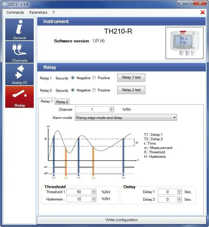
- Alarms: Set alarm modes (Rising edge, Falling edge, Control, Sensor state), thresholds, hysteresis, and delays for monostats and Class 310 transmitters.
- Inputs and Outputs: Modify output ranges (e.g., 4-20 mA, 0-10 V) and test analogue outputs.
- Air Velocity and Airflow: Select measuring means (Pitot, Debimo, etc.), enter correction coefficients, and set section dimensions for relevant transmitters.
- Relays: Configure relay security (Positive or Negative) and assign triggering conditions.
Other settings and maintenance
Advanced settings include:
- Self-calibration: Set the time-delay between self-calibrations for CP211-R and CP212-R.
- Integration: Adjust integration coefficients (0-9) to smooth pressure or velocity measurements.
- Purge: Configure purge mode for Class 310 transmitters to freeze measurements and block outputs during maintenance.
- Normative values: Select standards like DIN1343 or ISO2533.
- Firmware updates: Use the Bootloader menu to update the transmitter's internal software.
Manufacturer information
Sauermann
Practical help
Common problems
Software fails to read the transmitter
Ensure the transmitter is powered on and connected via the mini-DIN cable. For Class 110 and monostats, verify that the DIP switches are set to the 'ON' position.
Ethernet communication is not working
Verify that the address, mask, gateway, and port settings in the software match the network characteristics of the connected transmitter.
Before use
- Ensure the computer is running Windows XP, Vista, or 7.
- Verify the computer has a USB 2.0 port.
- Confirm at least 1 GB of RAM is available.
- Ensure 1 GB of free disk space is available.
- Power on the transmitter before connecting.
Show more Show less
Specs in practice
- Negative Security
- The relay is energised during an alarm condition.
- Positive Security
- The relay is de-energised during an alarm condition or power cut.
- Integration Coefficient (0-9)
- Averaging value to smooth measurements. 0 provides no integration (fast response), while 9 provides maximum integration (stable reading).
Images and diagrams
- DIP switch settings for Class 110 and monostat transmitters.
- Alarm mode graphs illustrating Rising edge, Falling edge, and Monitoring logic.
- Analogue output diagnostic table for testing 0-10V, 0-5V, 0-20mA, and 4-20mA signals.
Model compatibility
- Compatible with Sauermann Class 110, 210-R, 310, and monostats transmitters.
- Ethernet communication is not available on the CPE310-S model.
- Key beep is unavailable on the CPE310-S model.

Manual page author
Michael Turner
Technical manual editor