Industrial / Access Control
Installation Guide for SDC 1190AIWD Concealed Mortise Bolt Lock
Comprehensive installation and wiring guide for the SDC 1190AIWD Fail-Safe Concealed Mortise Bolt Lock. Includes mounting instructions for overhead and sidejamb applications, PR-1000 power regulator setup, electrical data, and...
Table of contents
Manual images
Click an image to enlargeQuick Guide from the Manual
The SDC 1190AIWD is a fail-safe concealed mortise bolt lock. Key installation steps involve mortising the door/frame, installing the lock, and connecting the power. The included PR-1000 Power Regulator is highly recommended for continuous duty to reduce heat and extend solenoid life. Ensure the power supply matches the 12VDC or 24VDC configuration of your unit.
Installation Instructions
Overhead Installation (Horizontal):
- Examine the top rail of the door for the strike plate location. Mark the door and header.
- Locate the center line of the door thickness on the header and attach the adhesive cutout template.
- Center punch the tab-mounting screw locations, counter-sink for #10 screws, and saw or rout the cutout area.
- Insert the lock (bolt end nearest the lock stile) and secure with #10-32 machine screws.
Sidejamb Installation (Vertical):
- Examine the lock stile jamb for the center of the door height. Mark the door stile and jamb.
- Attach the adhesive cutout template to the jamb, aligning the top of the cutout with the mark.
- Center punch and counter-sink for #10 screws, then saw or rout the cutout.
- Insert the lock (bolt at the top end of the cutout) and secure with #10-32 machine screws.
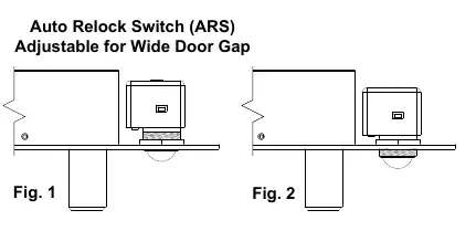
Auto Relock Switch (ARS) Adjustment
The ARS is set for a 1/8 inch clearance between the top of the door and the transom bar or head jamb. If there is a wider gap, loosen the lock nut and turn the switch assembly clockwise until the proper adjustment is reached. Tighten the lock nut securely after adjustment.
Wiring and Power
The PR-1000 Power Regulator is included to reduce power consumption after activation. DC voltage is recommended for optimal performance.
- 12VDC Configuration: 900mA (max).
- 24VDC Configuration: 450mA (max).
- Follow the provided wiring diagrams for connections with or without the PR-1000 regulator.
Troubleshooting
- Bolt does not project: Check voltage and alignment of the strike.
- Bolt projects but chatters: Voltage is too low.
- Bolt will not retract: Strike is mis-aligned.
Technical Data
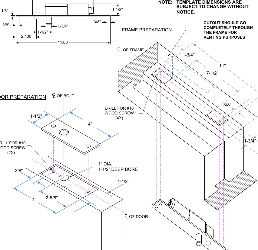
- Face Plate: 11" x 1-3/4" x 1/8"
- Strike: 4" x 1-1/2" x 1/8"
- Bolt: 3/4" diameter, solid stainless steel
- Bolt Throw: 3/4"
- PR-1000 Module: 3-3/4" x 1-1/4" x 1/2" (Required when mounted in frame)
Practical help
Common problems
Bolt does not project
Check voltage and alignment of the strike plate.
Bolt projects but chatters
Voltage is too low; ensure power supply meets requirements.
Bolt will not retract
Strike is mis-aligned; adjust position.
Before use
- Verify door type (Wood/Metal) and frame preparation.
- Ensure power supply matches 12VDC or 24VDC requirements.
- Confirm inclusion and wiring of the PR-1000 regulator.
- Check alignment of the strike plate before final mounting.
- Ensure the cutout is deep enough for the lock body.
Images and diagrams
- Fig 1/2: Shows how to adjust the Auto Relock Switch (ARS) for wide door gaps by loosening the nut and turning the assembly.
- Wiring diagrams: Illustrate connections for both 12VDC and 24VDC configurations, with and without the PR-1000 regulator.
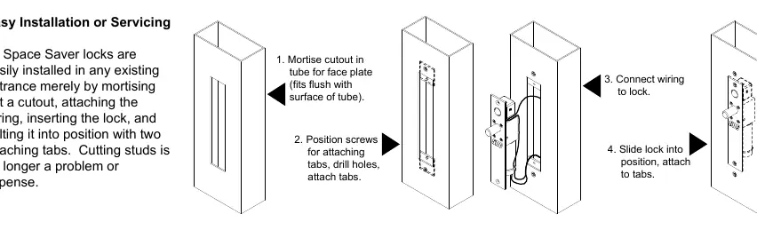
- Easy Installation: Visual sequence for mortising, attaching tabs, wiring, and sliding the lock into position.
Model compatibility
- Requires mortise cutout in door/frame.
- Compatible with 12VDC or 24VDC power sources.
- PR-1000 is required when mounted in the frame to prevent overheating.

Manual page author
Emily Carter
User documentation editor
Prepares concise manual descriptions and highlights the most useful setup, operation, and maintenance information for readers.