Industrial / Access Control
SDC 1291AHWD Fail-Secure Concealed Mortise Bolt Lock Installation Guide
Installation and wiring guide for the SDC 1291AHWD Fail-Secure Concealed Mortise Bolt Lock. Includes mounting instructions, PR-1000 regulator wiring, voltage configuration, and troubleshooting steps.
Table of contents
Manual images
Click an image to enlargeQuick Guide
The SDC 1291AHWD is a fail-secure concealed mortise bolt lock designed for access control. This guide covers installation, wiring with the included PR-1000 Power Regulator, and adjustment of the Auto Relock Switch (ARS). Ensure the power supply is compatible with 12VDC or 24VDC requirements before installation.
Installation Instructions
The lock can be installed in an overhead horizontal position or a sidejamb vertical position.
Overhead Installation (Horizontal)
- Examine the top rail of the door to locate the strike plate. Mark the door and header.
- Locate the center line of the door thickness on the header and attach the adhesive cutout template.
- Center punch the tab-mounting screw locations and counter-sink for #10 screws.
- Saw or rout out the cutout area.
Sidejamb Installation (Vertical)
- Examine the lock stile jamb for the point nearest the center of the door height.
- Mark the door stile for the top end of the strike plate and make a corresponding mark on the jamb.
- Attach the adhesive cutout template to the jamb, aligning the top of the cutout with the mark.
- Center punch the tab-mounting screw locations, counter-sink, and rout the cutout.
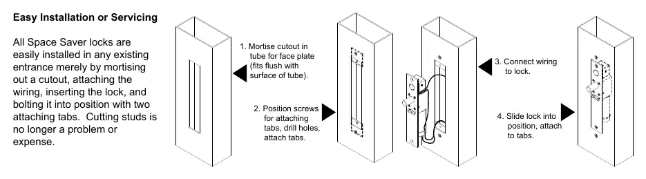
General Mounting
- Attach the mounting tabs inside the cutout.
- Attach power supply leads to the lock leads. Do not hang the lock by the wire leads.
- Insert the lock into the cutout. When installed horizontally, the bolt end must be nearest the lock stile. When installed vertically, the bolt must be at the top end of the cutout.
- Secure the lock with #10-32 machine screws.
- Use the strike plate as a template to mark and drill screw holes for the strike.
Auto Relock Switch (ARS) Adjustment
The ARS is set for a 1/8-inch clearance between the top of the door and the transom bar or head jamb. If there is an additional gap, compensate by:
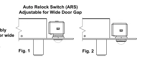
- Loosening the lock nut.
- Turning the switch assembly clockwise until the proper adjustment is reached.
- Tightening the lock nut securely.
Power Regulator and Wiring
The SDC PR-1000 Power Regulator is included to reduce power consumption and heat, extending the solenoid life. DC voltage is recommended for optimal performance.
Solenoid Voltage Configuration
- 24VDC: 450mA (max)
- 12VDC: 900mA (max)
Follow the wiring diagrams provided in the manual for connections with or without the PR-1000 regulator. Ensure the access control or push button (N/O) is correctly wired to the solenoid and power input.
Troubleshooting
- Bolt does not project: Check voltage and alignment of the strike.
- Bolt projects but chatters: Voltage is too low.
- Bolt will not retract: Strike is mis-aligned.
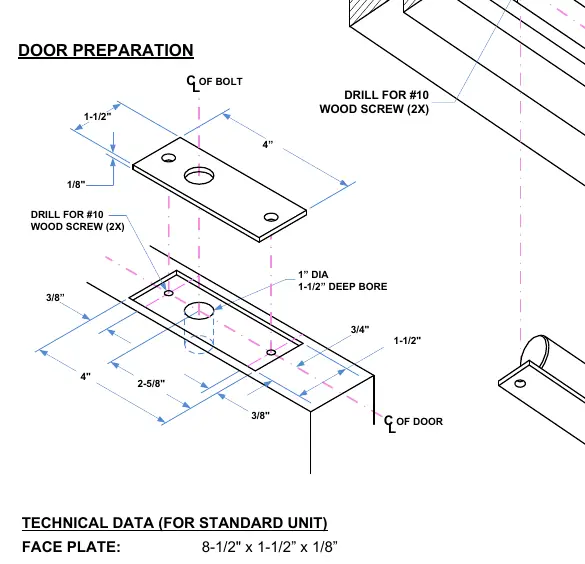
Technical Specifications
- Face Plate: 8-1/2" x 1-1/2" x 1/8"
- Strike: 4" x 1-1/2" x 1/8"
- Bolt: 5/8" diameter, solid stainless steel
- Bolt Throw: 3/4"
- PR-1000 Module: 3-3/4" x 1-1/4" x 1/2"
Practical help
Common problems
Bolt does not project
Check voltage and alignment of the strike.
Bolt projects but chatters
Voltage is too low.
Bolt will not retract
Strike is mis-aligned.
Before use
- Verify door type and frame compatibility.
- Ensure power supply matches 12VDC or 24VDC requirements.
- Confirm PR-1000 regulator is available for installation.
- Check for 1/8" clearance for the Auto Relock Switch.
- Ensure tools for mortising and drilling are available.
Images and diagrams
- Wiring diagrams show connections for both 12V and 24V configurations.
- Installation diagrams detail mortise cutout dimensions for door and frame.
- ARS adjustment diagram shows how to loosen the nut and turn the assembly.
Model compatibility
- Requires PR-1000 regulator for optimal solenoid life and heat reduction.
- Designed for concealed mortise installation.

Manual page author
David Miller
Documentation analyst
Organizes user manual content into clear summaries, with attention to model details, product context, and everyday usability.