Industrial / Access Control
Installation Guide for SDC 1091AI and 1091AIDL Fail-Safe Concealed Mortise Bolt Lock
A comprehensive installation and wiring guide for the SDC 1091AI and 1091AIDL Fail-Safe Concealed Mortise Bolt Lock. Includes detailed mounting instructions, wiring diagrams for 12VDC and 24VDC configurations, PR-1000 regulator setup, and...
Table of contents
Manual images
Click an image to enlargeQuick Guide for Installation
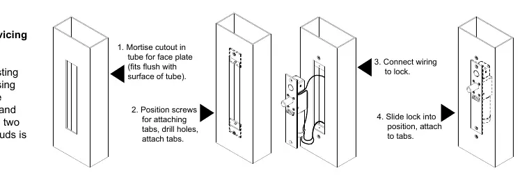
The SDC 1091AI and 1091AIDL are fail-safe concealed mortise bolt locks designed for metal doors and frames. Installation involves mortising a cutout in the door or frame, attaching the wiring, and securing the lock with two mounting tabs. The system includes an Auto Relock Switch (ARS) and requires a PR-1000 Power Regulator for frame-mounted applications to manage heat and power consumption.
Installation Instructions
Overhead Installation (Horizontal):
- Examine the top rail of the door for the strike plate location. Mark the door and the header to align the strike plate and lock.
- Locate the center line of the door thickness on the header. Attach the adhesive cutout template.
- Center punch the tab-mounting screw locations and counter-sink for #10 screws. Saw or rout out the cutout area.
Sidejamb Installation (Vertical):
- Examine the lock stile jamb for the point nearest the center of the door height.
- Mark the door stile horizontal for the top end of the strike plate and make a corresponding mark on the jamb.
- Attach the adhesive cutout template to the jamb, aligning the top of the cutout with the horizontal mark.
- Center punch the tab mounting screw locations, counter-sink for #10 screws, and saw or rout the cutout.
Finalizing Installation:
- Attach mounting tabs inside the cutout.
- Connect power supply leads to the lock leads. Do not hang the lock by the wire leads.
- Insert the lock into the cutout. When installed horizontally, the bolt end must be nearest the lock stile. When installed vertically, the bolt must be at the top end of the cutout. Secure with #10-32 machine screws.
- Use the strike plate as a template to mark and drill screw holes. Mortise as required and attach the strike.
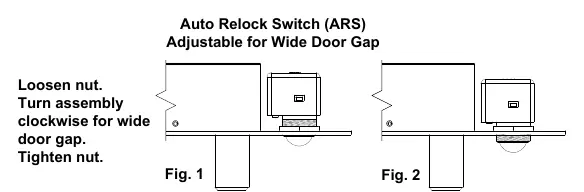
Auto Relock Switch (ARS) Adjustment
The ARS is factory-set for a 1/8" clearance between the top of the door and the transom bar or head jamb. If there is an additional gap, compensate by loosening the lock nut and turning the switch assembly clockwise until the adjustment is satisfactory. Ensure the lock nut is tightened after adjustment.
Wiring and Power Configuration
The SDC PR-1000 Power Regulator is included and recommended for use to reduce power consumption and heat, extending the life of the solenoid. The lock supports dual voltage (12VDC or 24VDC).
- 12VDC Configuration: 0.9 Amp (Max) Continuous Duty.
- 24VDC Configuration: 0.45 Amp (Max) Continuous Duty.
- Wiring: Follow the provided diagrams for connections with or without the PR-1000 regulator. Ensure correct polarity for the solenoid and sensors (BPS/DPS).
Troubleshooting
- Bolt does not project: Check voltage and alignment of the strike.
- Bolt projects but chatters: Voltage is too low.
- Bolt will not retract: Strike is mis-aligned.
Technical Data
- Face Plate: 8" x 1-1/2" x 1/8"
- Strike: 4" x 1-1/2" x 1/8"
- Bolt: 5/8" diameter solid stainless steel
- Bolt Throw: 3/4"
- PR-1000 Module: 3-3/4" x 1-1/4" x 1/2" (Required when mounted in frame)
Practical help
Common problems
Bolt does not project
Check voltage and alignment of the strike plate.
Bolt projects but chatters
Voltage is too low; ensure power supply meets requirements.
Bolt will not retract
The strike is mis-aligned; adjust the strike plate position.
Before use
- Verify the door and frame are metal.
- Ensure the power supply is 12VDC or 24VDC.
- Confirm the PR-1000 Power Regulator is available for frame mounting.
- Check for 1/8" clearance for the Auto Relock Switch.
- Ensure #10-32 machine screws are available for securing the lock.
Specs in practice
- Bolt Material
- 5/8" diameter solid stainless steel.
Images and diagrams
- Wiring diagrams illustrate connections for both 12VDC and 24VDC configurations.
- Diagrams show the integration of the PR-1000 Power Regulator to reduce heat.
- Installation diagrams provide specific cutout dimensions for door and frame preparation.
Model compatibility
- Designed for metal doors and frames.
- PR-1000 module is required when the lock is mounted in the frame.

Manual page author
Emily Carter
User documentation editor
Prepares concise manual descriptions and highlights the most useful setup, operation, and maintenance information for readers.