Industrial / Access Control
Installation Guide for SDC 1291AHDDMR1 Concealed Mortise Bolt Lock
Quick installation guide for the SDC 1291AHDDMR1 Concealed Mortise Bolt Lock. Includes wiring diagrams for 12VDC/24VDC, door preparation dimensions, and sensor configuration.
Table of contents
Manual images
Click an image to enlargeQuick Guide for Installation
The SDC 1291AHDDMR1 is a concealed mortise bolt lock with mechanical release, designed for fail-secure operation. This unit requires specific door and frame preparation and supports dual voltage (12VDC or 24VDC). Ensure you have a standard straight cam (ILCO 863G or equivalent) for the cylinder installation.
Door and Frame Preparation
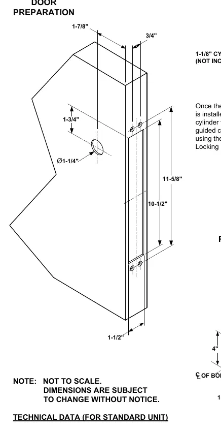
Proper preparation is critical for the installation of the mortise bolt lock. Refer to the provided dimensions for the door and frame cutouts. The installation requires tapping tabs for #10-32 screws. Ensure the backset is 1-7/8 inches as specified for this model.
Cylinder Installation
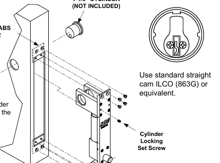
Once the key cylinder is inserted into the lock, it must be secured within the guided cylinder slot. Use the provided Cylinder Locking Set screw to fasten the cylinder in place. Ensure the cylinder uses a standard straight cam.
Wiring and Electrical Configuration
The lock is pre-wired with a pigtail connector. Select the appropriate configuration based on your power supply:
- 12VDC Solenoid Configuration: Connect the pigtail wires according to the 12VDC diagram. Ensure the power input matches the 12VDC requirement.
- 24VDC Solenoid Configuration: Connect the pigtail wires according to the 24VDC diagram. Ensure the power input matches the 24VDC requirement.
- Unused Wires: Cap any unused wires to prevent short circuits.
Sensor Configuration
The unit may include optional sensors:
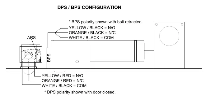
- Bolt Position Sensor (BPS-Magnetic): Indicates if the bolt is locked or unlocked (5 Watt).
- Door Position Switch (DPS-Mechanical): Indicates if the door is opened or closed (4A @ 30VDC Resistive).
The polarity for BPS is shown with the bolt retracted, and the polarity for DPS is shown with the door closed.
Technical Specifications
- Face Plate: 10-1/2" x 1-1/2" x 1/8"
- Strike: 4" x 1-1/2" x 1/8"
- Bolt: 5/8" diameter, stainless steel
- Bolt Throw: 3/4"
- Backset: 1-7/8"
- Power Requirements: 12VDC @ 0.9 Amp (Max) or 24VDC @ 0.45 Amp (Max)
Practical help
Common problems
Incorrect voltage selection
Ensure the power input matches the 12VDC or 24VDC solenoid configuration diagram provided in the manual.
Bolt not locking or unlocking
Verify wiring polarity and ensure the pigtail connector is securely attached to the power source.
Cylinder does not fit or operate
Ensure you are using a standard straight cam (ILCO 863G or equivalent) and that the cylinder is secured with the locking set screw.
Before use
- Verify power supply voltage (12VDC or 24VDC).
- Ensure the door and frame are prepared according to the provided dimensions.
- Confirm the use of a standard straight cam (ILCO 863G).
- Check that the cylinder is secured with the locking set screw.
- Cap all unused wires.
Specs in practice
- 12VDC Solenoid
- Requires 0.9 Amp (Max) Continuous Duty.
- 24VDC Solenoid
- Requires 0.45 Amp (Max) Continuous Duty.
- BPS (Bolt Position Sensor)
- Indicates if the bolt is locked or unlocked (5 Watt).
- DPS (Door Position Switch)
- Indicates if the door is opened or closed (4A @ 30VDC Resistive).
Images and diagrams
- The Door Preparation diagram shows the required cutouts and tap locations for the lock body.
- The Frame Preparation diagram details the strike plate cutout and mounting holes.
- Wiring diagrams illustrate the specific connections for 12VDC and 24VDC power inputs.
- The DPS/BPS configuration diagram shows the color-coded wire connections for the sensors.
Model compatibility
- Requires standard straight cam (ILCO 863G or equivalent).
- Fail-secure operation.
- Double cylinder prep.

Manual page author
Emily Carter
User documentation editor
Prepares concise manual descriptions and highlights the most useful setup, operation, and maintenance information for readers.