Industrial / Access Control
Installation Guide for SDC 1291AHDMR Concealed Mortise Bolt Lock
A comprehensive installation guide for the SDC 1291AHDMR Concealed Mortise Bolt Lock. This manual provides detailed instructions for frame and door preparation, mounting block reversal, and electrical wiring configurations for 12VDC and...
Table of contents
Manual images
Click an image to enlargeQuick Guide for Installation
The SDC 1291AHDMR is a concealed mortise bolt lock designed for fail-secure operation. This document provides the necessary steps for frame and door preparation, as well as electrical wiring. Please note that the 1-1/8 inch cylinder is not included and must be sourced separately. Ensure you use a standard straight cam ILCO (863G) or equivalent cylinder for proper operation.
Technical Data
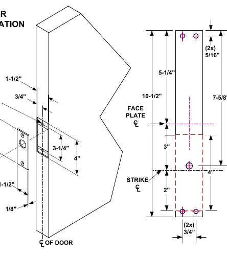
- Face Plate: 10-1/2 inches x 1-1/2 inches x 1/8 inch
- Strike: 4 inches x 1-1/2 inches x 1/8 inch
- Bolt: 5/8 inch diameter, stainless steel
- Bolt Throw: 3/4 inch
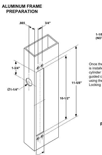
- Back Set: .865 inch
- Dual Voltage Solenoid: 12VDC at 0.9 Amp (Max) or 24VDC at 0.45 Amp (Max)
Frame and Door Preparation
The installation requires precise cutting of the frame and door. Refer to the specific diagrams for your frame type (Aluminum or Hollow Metal). Ensure all tap tabs are prepared for #10-32 screws as indicated in the diagrams. The door preparation requires a cutout for the face plate and strike, ensuring the bolt aligns correctly with the strike plate.
Reversing the Mounting Block
If the mounting block orientation needs to be changed, follow these steps:
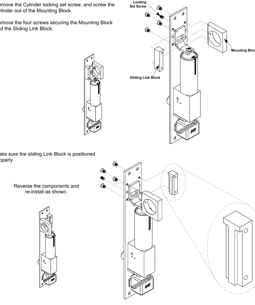
- Remove the cylinder locking set screw and unscrew the cylinder from the mounting block.
- Remove the four screws securing the mounting block and the sliding link block.
- Reverse the components and re-install them as shown in the diagram.
- Ensure the sliding link block is positioned properly before securing the screws.
Wiring and Electrical Connections
The lock supports both 12VDC and 24VDC configurations using the provided pigtail connector. Select the appropriate configuration based on your power supply:
- 24VDC Configuration: Connect the red (+) and white (-) wires to the 24VDC power input. Cap unused wires.
- 12VDC Configuration: Connect the red (+) and white (-) wires to the 12VDC power input.
Optional sensors are available: Bolt Position Sensor (BPS-Magnetic) indicates if the bolt is locked or unlocked (5 Watt), and Door Position Sensor (DPS-Mechanical) indicates if the door is opened or closed (4A at 30VDC Resistive). When both options are ordered, the common wire is shared.
Practical help
Common problems
Bolt does not retract or extend properly
Verify that the voltage configuration (12VDC vs 24VDC) matches your power supply and that the pigtail connector is wired correctly.
Mounting block orientation is incorrect
Follow the 'Instructions for Reversing the Mounting Block' on page 4 to reorient the sliding link block.
Before use
- Verify the frame type (Aluminum or Hollow Metal) and follow the corresponding preparation diagram.
- Ensure you have a 1-1/8 inch cylinder (not included).
- Confirm the use of a standard straight cam ILCO (863G) or equivalent cylinder.
- Check that your power supply matches the 12VDC or 24VDC solenoid configuration.
- Ensure all #10-32 tap tabs are prepared correctly.
Specs in practice
- Continuous Duty
- The solenoid is designed to remain powered for extended periods without overheating.
Images and diagrams
- Wiring diagrams illustrate the connection of the pigtail connector for both 12VDC and 24VDC power inputs.
- Frame preparation diagrams provide exact dimensions for cutting the frame to accommodate the lock body.
- Door preparation diagrams show the placement of the face plate and strike plate.
Model compatibility
- Requires a standard straight cam ILCO (863G) or equivalent cylinder.
- Fail-secure operation: The lock remains locked when power is lost.
- Optional BPS and DPS sensors share a common wire if both are installed.

Manual page author
Michael Turner
Technical manual editor
Reviews PDF manuals for structure, safety notes, and practical product details so readers can find the right information quickly.