Industrial / Access Control
SDC 1291AH Fail-Secure Concealed Mortise Bolt Lock Installation Guide
Comprehensive installation and wiring guide for the SDC 1291AH Fail-Secure Concealed Mortise Bolt Lock. Includes step-by-step mounting instructions, PR-1000 power regulator wiring diagrams, Auto Relock Switch (ARS) adjustments, and...
Table of contents
Manual images
Click an image to enlargeQuick Guide
The SDC 1291AH is a fail-secure concealed mortise bolt lock designed for metal doors and frames. This guide covers the installation process, wiring requirements, and necessary adjustments for the Auto Relock Switch (ARS). Always handle the lock carefully and do not hang it by the wire leads during installation.
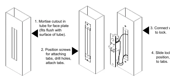
Installation Instructions
The lock can be installed in two configurations: Overhead Horizontal or Sidejamb Vertical.
Overhead Installation (Horizontal)
- Examine the top rail of the door to locate the strike plate position.
- Mark the door for the end of the strike closest to the lock stile and make a corresponding mark on the header.
- Locate the center line of the door thickness on the header and attach the adhesive cutout template.
- Center punch the tab-mounting screw locations and counter-sink for #10 screws.
- Saw or rout out the cutout area.
- Attach mounting tabs inside the header.
- Insert the lock; the bolt end must be nearest the lock stile.
- Secure with #10-32 machine screws.
Sidejamb Installation (Vertical)
- Examine the lock stile jamb for the point nearest the center of the door height.
- Mark the door stile horizontal for the top end of the strike plate and make a corresponding mark on the jamb.
- Locate the center line of the door thickness on the jamb and attach the adhesive cutout template.
- Center punch the tab-mounting screw locations and counter-sink for #10 screws.
- Saw or rout out the frame cutout.
- Attach mounting tabs inside.
- Insert the lock; the bolt must be at the top end of the cutout.
- Secure with #10-32 machine screws.
Auto Relock Switch (ARS) Adjustment
The ARS is set for 1/8 inch clearance between the top of the door and the transom bar or head jamb. If there is an additional gap:
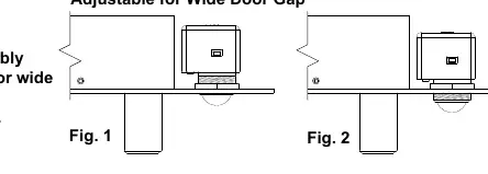
- Loosen the lock nut.
- Turn the switch assembly clockwise until proper adjustment is reached.
- Tighten the lock nut securely.
Wiring and Power
The SDC PR-1000 Power Regulator is included and recommended to reduce power consumption and heat, extending the life of the solenoid. DC voltage is recommended for optimal performance.
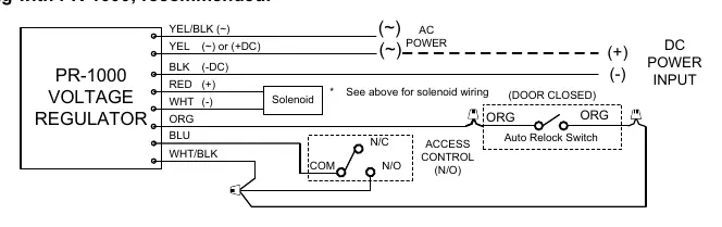
Wiring with PR-1000 (Recommended)
- Connect the PR-1000 module between the power source and the lock.
- Follow the wiring diagram provided in the manual to connect the YEL/BLK, YEL, BLK, RED, WHT, ORG, and BLU leads correctly.
- Ensure the access control (N/O) and Auto Relock Switch are integrated as shown in the wiring schematic.
Troubleshooting
- Bolt will not retract: Check the voltage and the alignment of the strike.
- Bolt does not project: The strike is likely mis-aligned.
Technical Data
- Face Plate: 8" x 1-1/2" x 1/8"
- Strike: 4" x 1-1/2" x 1/8"
- Bolt: 5/8" diameter solid stainless steel
- Bolt Throw: 3/4"
- PR-1000 Module: 3-3/4" x 1-1/4" x 1/2" (Required when mounted in frame)
- Solenoid 12VDC: 0.9 Amp (Max) Continuous Duty
- Solenoid 24VDC: 0.45 Amp (Max) Continuous Duty
For further assistance, contact SDC via their website or email [email protected].
Practical help
Common problems
Bolt will not retract
Check voltage and alignment of strike.
Bolt does not project
Strike is mis-aligned.
Before use
- Verify door frame material is suitable for mortise installation.
- Ensure power supply matches solenoid requirements (12VDC or 24VDC).
- Confirm PR-1000 regulator is available for installation.
- Check clearance for Auto Relock Switch (ARS) (1/8 inch).
- Ensure #10-32 machine screws are available for securing the lock.
Specs in practice
- Continuous Duty
- The solenoid is rated to remain powered for extended periods, though PR-1000 is recommended to reduce heat.
Images and diagrams
- Wiring diagrams illustrate connections for both 12VDC and 24VDC configurations.
- Installation diagrams show the mortise cutout dimensions for the door and frame.
Model compatibility
- PR-1000 module is required when mounted in the frame.
- Designed for metal door and frame installation.

Manual page author
David Miller
Documentation analyst
Organizes user manual content into clear summaries, with attention to model details, product context, and everyday usability.