Industrial / Electrical
Instruction Manual for Seaflo 02-Series Float Switch
Quick guide for the Seaflo 02-Series float switch, covering installation, wiring, safety precautions, and operational principles for marine bilge pump systems.
Table of contents
Manual images
Jump to the sectionQuick guide from the manual
The Seaflo 02-Series float switch is designed for automatic control of bilge pumps in marine environments. This document outlines the correct installation, wiring, and safety requirements to ensure reliable operation and prevent pump failure or electrical hazards.
Safety and installation requirements
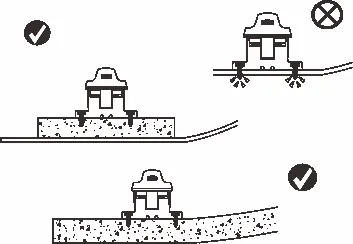
- The switch must be mounted at or above the pump base level to ensure positive shut-off.
- All mounting holes must be sealed with marine-grade sealant to prevent water intrusion.
- Keep all wire connections above the highest water level and use connectors with marine-grade sealant to prevent wire corrosion.
- Always install a proper size fuse to prevent damage and fire hazards.
- This unit is designed for fresh water and salt water only. Do not use with hazardous, caustic, or corrosive materials.
- Do not use with 110V AC power.
Installation
Ensure the switch is mounted on a flat surface. The device should be positioned so that the float can move freely without obstruction. Secure the base using appropriate screws, ensuring the mounting surface is stable. The switch should be installed within a maximum angle of 5 degrees to ensure proper activation.
Wire connection
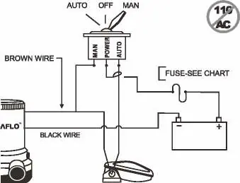
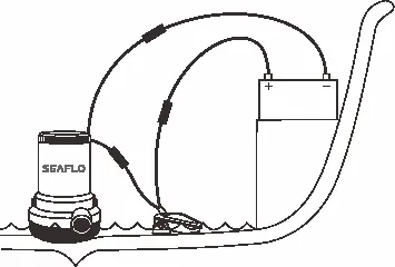
Connect the switch in series with the positive power lead of the bilge pump. Use the provided wiring diagram to ensure the brown wire is connected to the pump and the black wire is connected to the negative terminal of the battery. Ensure all connections are waterproof and protected from the elements.
Work principle
The switch operates based on water level. It activates the pump when the water level reaches approximately 60mm and turns it off when the water level drops to approximately 30mm.
Testing the float switch
To test the unit, manually lift the float to verify that the pump activates. Ensure the float moves smoothly without catching on any debris or mounting hardware.
Manufacturer information
Seaflo
Practical help
Common problems
Pump does not turn off
Check if the float is obstructed by debris or if the switch is mounted incorrectly.
Wire corrosion
Ensure all wire connections are kept above the water level and sealed with marine-grade sealant.
Water intrusion in mounting holes
Seal all mounting holes with marine-grade sealant during installation.
Before use
- Verify the power source is 12V or 24V DC (do not use 110V AC).
- Ensure a proper fuse is installed in the circuit.
- Check that the switch is mounted at or above the pump base level.
- Confirm all wire connections are waterproof.
- Test the float movement for any obstructions.
Images and diagrams
- The wiring diagram shows the switch connected in series with the pump and battery.
- The work principle diagram illustrates the 60mm ON and 30mm OFF water level thresholds.
Model compatibility
- Designed for fresh water and salt water only.
- Not compatible with hazardous, caustic, or corrosive liquids.
- Ignition protected.

Manual page author
Michael Turner
Technical manual editor
Reviews PDF manuals for structure, safety notes, and practical product details so readers can find the right information quickly.