Industrial / Electrical
SEAFLO Solenoid Valve & Siphon Breaker Instruction Manual
Comprehensive installation and operation guide for SEAFLO SFSV1-01 and SFSV2-01 solenoid valve and siphon breaker assemblies, including wiring diagrams and safety precautions.
Table of contents
Manual images
Jump to the sectionProduct Overview
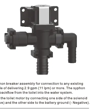
The SEAFLO solenoid valve and siphon breaker assembly is a critical component designed for integration into existing pressurized water systems. It is specifically engineered to support marine or recreational vehicle toilet systems that require a flow rate of at least 2.9 gallons per minute (11 liters per minute). The primary function of this device is to act as a siphon breaker, ensuring that there is no backflow from the toilet into the fresh water system, thereby protecting the integrity of your water supply.
Installation and Wiring
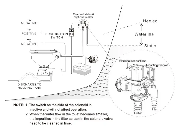
Proper installation is essential for the safe and effective operation of the solenoid valve. The unit should be mounted securely using the provided mounting bracket. When wiring the solenoid, it must be connected in parallel with the toilet motor. Connect one side of the solenoid to the toilet flush switch (positive terminal) and the other side to the battery ground (negative terminal). This configuration ensures that the valve operates in sync with the flushing mechanism.
Safety and Operational Limits
Safety is paramount when dealing with electrical water valves. The solenoid is designed for use with either 12V DC or 24V DC power sources, depending on your specific model. It is critical to note that the solenoid should not be operated for more than 30 seconds continuously. Running the device beyond this duty cycle can lead to overheating and permanent damage to the internal components. Always ensure the electrical connections are secure and protected from moisture to prevent short circuits.
Maintenance and Troubleshooting
To ensure the longevity of your SEAFLO solenoid valve, regular maintenance is recommended. If you notice that the water flow into the toilet becomes restricted or smaller than usual, it is likely that the filter screen inside the solenoid valve has become clogged with debris. In such cases, the filter screen must be cleaned promptly to restore proper flow. The switch located on the side of the solenoid is inactive and does not affect the normal operation of the device. By keeping the filter clean and adhering to the duty cycle limits, you can ensure reliable performance of your water system for years to come.
Manufacturer information
Seaflo
Practical help
Common problems
Reduced water flow into the toilet
Clean the impurities from the filter screen inside the solenoid valve.
Solenoid overheating or failure
Ensure the device does not run for more than 30 seconds continuously.
Before use
- Verify the water system provides at least 2.9 gpm (11 lpm).
- Confirm the voltage matches your model (12V DC or 24V DC).
- Ensure the solenoid is wired in parallel with the toilet motor.
- Check that the mounting bracket is securely fastened.
- Confirm the positive and negative connections are correct.
Images and diagrams
- The wiring diagram shows the solenoid connected in parallel with the toilet flush switch.
- The dimension drawing provides exact measurements for installation clearance.
- The system diagram illustrates the connection between the water tank, solenoid, and toilet.
Model compatibility
- Compatible with pressurized water systems delivering 2.9 gpm or more.
- SFSV1-01 is designed for 12V DC systems.
- SFSV2-01 is designed for 24V DC systems.

Manual page author
Emily Carter
User documentation editor
Prepares concise manual descriptions and highlights the most useful setup, operation, and maintenance information for readers.