Industrial / I/O Modules
User Manual for Siemens SIMATIC ET 200SP F-DI 8x24VDC HF Digital Input Module
Comprehensive user guide for the Siemens SIMATIC ET 200SP F-DI 8x24VDC HF digital input module. Includes installation, wiring, parameter configuration, safety application modes, and diagnostic troubleshooting.
Quick answers from the manual
Quick answer
- The F-DI 8x24VDC HF is a fail-safe digital input module for the SIMATIC ET 200SP system, supporting SIL3/Cat.4/PLe safety applications. p. 9, 10
Key actions
- Configuration p. 15
First start
- Ensure correct BaseUnit (A0) is used, supply voltage is connected, and parameters are configured in STEP 7. p. 13, 15
Problems and fixes
Overtemperature
Operate within specified temperature range.
p. 47
Load voltage missing
Check supply voltage L+ at BaseUnit.
p. 47Maintenance and reset
- Reintegrate the module in the safety program after eliminating the fault. p. 47
Technical specifications
| Parameter | Value | Meaning | Pages |
|---|---|---|---|
| Number of inputs | 8 | Digital inputs | p. 54 |
| Supply voltage | 24 V DC | Rated value | p. 53 |
| Width | 15 mm | Module width | p. 55 |
Where to find it in the PDF
- Product overview p. 9, 10
- Connecting p. 13, 14
- Parameters p. 15, 16, 17
- Applications p. 29, 30, 31, 34
- Diagnostics p. 43, 47
- Technical specifications p. 53, 54, 55
Table of contents
Manual images
Click an image to enlargeQuick guide from the manual
The Siemens SIMATIC ET 200SP F-DI 8x24VDC HF is a fail-safe digital input module designed for use in safety-critical automation systems. It supports SIL3/Cat.4/PLe safety levels. Key tasks include proper wiring on a compatible BaseUnit, configuring parameters in STEP 7, and monitoring diagnostic LEDs for system status.
Product overview
The module features 8 fail-safe inputs and 8 outputs for sensor supply. It supports various interconnection types (1oo1, 1oo2) and provides channel-specific diagnostics such as short-circuit and wire-break detection. Supported functions include firmware updates, I&M identification data, and PROFIsafe communication.
Installation and wiring
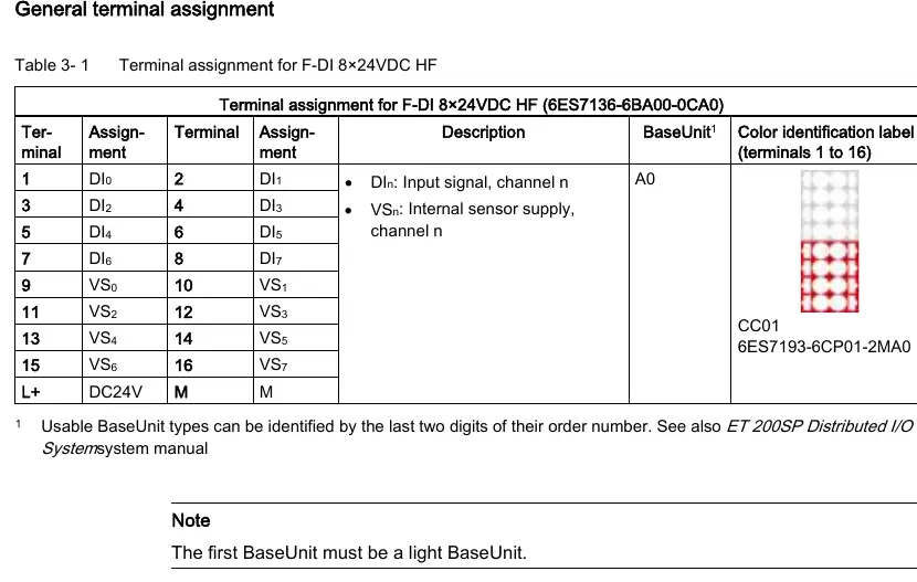
Wiring is performed on the matching BaseUnit (Type A0). The module supports both internal and external sensor supplies. Ensure that the first BaseUnit in the configuration is a light BaseUnit. The module provides terminal assignments for input signals (DI0 to DI7) and sensor supplies (VS0 to VS7).
Configuration and parameters
Parameters are configured in STEP 7. Key parameters include:
- Sensor evaluation: 1oo1 or 1oo2 (equivalent/non-equivalent).
- Short circuit test: Enabled/disabled for internal sensor supply.
- Input delay: Adjustable from 0.4 ms to 20 ms to suppress interference.
- Discrepancy time: Configurable for channel pairs to detect signal differences.
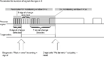
- Chatter monitoring: Detects unusual signal sequences.
Safety applications
The module supports different safety modes depending on the wiring and sensor configuration:
- Application 1: SIL3/Cat.3/PLd using 1oo1 evaluation.
- Application 2: SIL3/Cat.3/PLe using 1oo2 evaluation (equivalent).
- Application 3: SIL3/Cat.4/PLe using 1oo2 evaluation (equivalent or non-equivalent).
Always ensure sensors are suitably qualified for the intended safety level.
Diagnostics and troubleshooting
The module provides diagnostic interrupts and LED indicators:
- DIAG LED: Indicates module status (green/red).
- Channel status/fault LED: Indicates signal state and channel-specific faults.
- PWR LED: Indicates supply voltage status.
If a fault occurs, consult the diagnostic message table to identify the fault code and follow the recommended remedy, such as checking wiring, replacing the sensor, or correcting parameter assignments.
Technical specifications
The module operates on 24 V DC. It has a width of 15 mm and weighs approximately 49 g. Operating temperature ranges from 0 °C to 60 °C (horizontal installation). It is designed for SIL 3 safety functions.
Manufacturer information
Siemens AG
Practical help
Common problems
Module passivated / DIAG LED flashing
Check supply voltage L+, verify parameter configuration, or check for short circuits.
Discrepancy error
Check process signal, verify sensor functionality, check wiring, or adjust discrepancy time.
No pulse detected
Check pulse monitoring window settings, minimum pulse time, or process wiring for breaks.
Before use
- Ensure the module is used with a compatible BaseUnit (Type A0).
- Verify the supply voltage L+ is within 20.4 V to 28.8 V DC.
- Configure parameters in STEP 7 according to the required safety application (SIL3/Cat.3 or Cat.4).
- Ensure sensors are qualified for the intended safety level.
Specs in practice
- SIL3/Cat.4/PLe
- Highest safety standards for industrial automation.
- 1oo1 evaluation
- Single channel sensor evaluation.
- 1oo2 evaluation
- Two-channel sensor evaluation for redundancy.
Images and diagrams
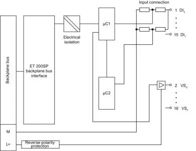
- Block diagram shows the internal structure, including backplane bus interface, electrical isolation, and input/sensor supply connections.
- Chatter monitoring diagram illustrates how signal changes are counted within a monitoring window to detect faulty sensors.
Model compatibility
- Compatible with ET 200SP distributed I/O system.
- Requires BaseUnit type A0.

Manual page author
Michael Turner
Technical manual editor
Reviews PDF manuals for structure, safety notes, and practical product details so readers can find the right information quickly.