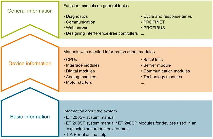
Industrial / I/O Modules
Equipment Manual for Siemens SIMATIC ET 200SP Analog Input Module 6ES7134-6JF00-0CA1
Comprehensive equipment manual for the Siemens SIMATIC ET 200SP AI 8xRTD/TC 2-wire HF analog input module (6ES7134-6JF00-0CA1). Includes wiring diagrams, parameter configuration, diagnostic alarm troubleshooting, and technical...
Quick answers from the manual
Quick answer
- The Siemens SIMATIC ET 200SP AI 8xRTD/TC 2-wire HF (6ES7134-6JF00-0CA1) is an 8-channel analog input module supporting RTD, TC, resistor, and voltage measurements. p. 13
Key actions
- Configure parameters via STEP 7 or GSD file. p. 22
- Deactivate unused channels to shorten cycle time. p. 26
Problems and fixes
Wire break
Use a different sensor type, modify wiring, or connect/deactivate the channel.
p. 46Error codes
| Code | Meaning | Action | Pages |
|---|---|---|---|
| 6H | Wire break | Use a different sensor type or modify the wiring. | p. 46 |
| 11H | Supply voltage missing | Check the supply voltage L+ at the BaseUnit. | p. 46 |
Technical specifications
| Parameter | Value | Meaning | Pages |
|---|---|---|---|
| Supply voltage | 24 V DC | Rated supply voltage | p. 48 |
| Width | 15 mm | Module width | p. 53 |
Where to find it in the PDF
- Product Overview p. 13
- Technical Specifications p. 48
Table of contents
Manual images
Click an image to enlargeQuick guide from the manual
This manual provides technical information for the Siemens SIMATIC ET 200SP AI 8xRTD/TC 2-wire HF module. It covers installation, wiring, parameterization, and diagnostics for the 6ES7134-6JF00-0CA1 module.
Product Overview
The module is an analog input device with 8 inputs. It supports four measurement types, configurable per channel:
- Thermal resistor (RTD)
- Thermocouple (TC)
- Resistor
- Voltage
It features a resolution of up to 16 bits including sign, configurable diagnostics per channel, and hardware interrupts on limit violations.
Wiring
The module must be used with a compatible BaseUnit. The load group must begin with a light-colored BaseUnit. When using floating sensors, bridge the m- connections and connect to ground/FE to increase immunity. Bridging is not required for disabled inputs.
Parameters
Module properties are configured via STEP 7 or GSD files. Key parameters include:
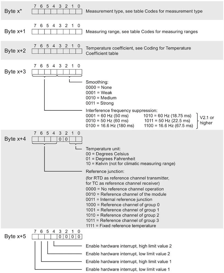
- Interference frequency suppression: Adjustable to 50 Hz, 60 Hz, or 16.6 Hz.
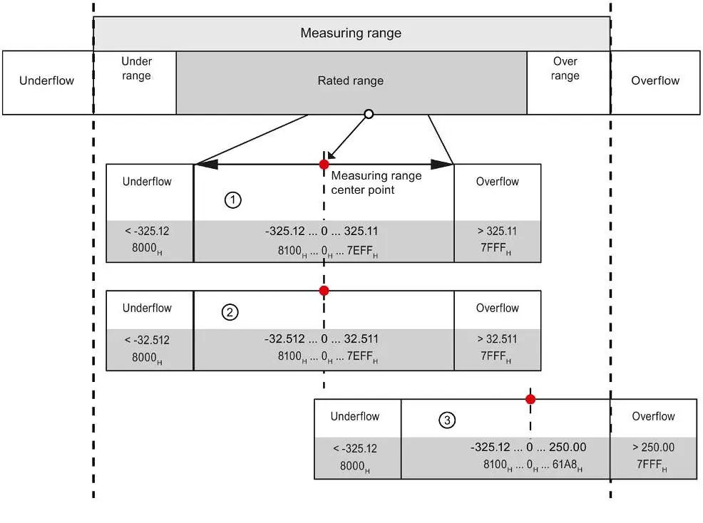
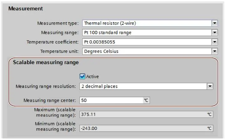
- Scalable measuring range: Allows increased resolution for a specific section of the measuring range.
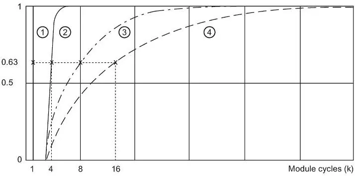
- Smoothing: Adjustable in 4 levels (None, Weak, Medium, Strong).
- Hardware interrupts: Configurable high and low limits for each channel.
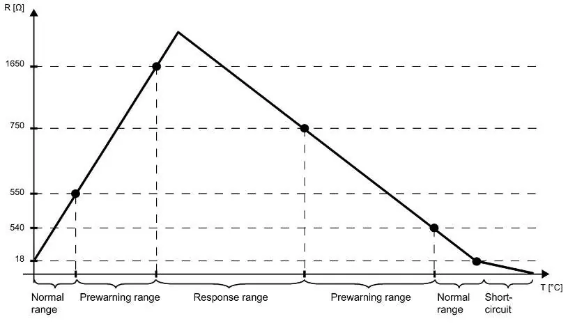
Diagnostics
The module provides diagnostic information via the DIAG LED and CPU diagnostics buffer. Common diagnostic events include wire break, supply voltage missing, and parameter assignment errors. The DIAG LED flashes red when module diagnostics are present.
Technical Specifications
The module operates on 24V DC. It supports a wide range of sensors and thermocouples. The module width is 15 mm.
Manufacturer information
Siemens AG
Practical help
Common problems
Wire break diagnostic
Check sensor wiring, ensure cables are connected, or deactivate diagnostics if the channel is unused.
Supply voltage missing
Check the 24V DC supply at the BaseUnit and verify the BaseUnit type.
Reference channel error
Check BaseUnit type and ensure the reference junction is correctly assigned through parameterization.
Before use
- Ensure the BaseUnit is correctly installed.
- Verify the 24V DC power supply.
- Check sensor compatibility (RTD, TC, Resistor, Voltage).
- Configure parameters in STEP 7 or via GSD file.
- Ensure unused channels are deactivated to shorten cycle time.
Specs in practice
- Cable length
- Max 200m shielded; 50m with thermocouples.
Images and diagrams
- The wiring diagram shows terminal assignments for 2-wire connections on BaseUnit BU type A0/A1.
- The LED display section identifies DIAG, Channel status, Channel error, and PWR LEDs.
Model compatibility
- Requires STEP 7 TIA Portal V16 or higher, or STEP 7 V5.5 SP3 or higher.
- Compatible with BaseUnit types A0 and A1.

Manual page author
Michael Turner
Technical manual editor
Reviews PDF manuals for structure, safety notes, and practical product details so readers can find the right information quickly.