Industrial / I/O Modules
Siemens SIMATIC ET 200SP Server Module User Manual
Quick guide for the Siemens SIMATIC ET 200SP Server Module (6ES7193-6PA00-0AA0). Learn about installation, configuration, address space mapping, and diagnostics.
Quick answers from the manual
Quick answer
- The SIMATIC ET 200SP Server Module (6ES7193-6PA00-0AA0) terminates the backplane bus of the ET 200SP system, provides support for 3 spare fuses, and enables diagnostics for supply voltage L+ and feedback voltage. p. 8
Key actions
- Configure module p. 8, 9
- Update firmware p. 17
First start
- Installation p. 8
Problems and fixes
Invalid firmware
Error code 1BH indicates invalid firmware (< V1.1.1). Replace module or update firmware.
p. 17Error codes
| Code | Meaning | Action | Pages |
|---|---|---|---|
| 1BH | General error (invalid firmware version) | Replace module or update firmware | p. 17 |
Technical specifications
| Parameter | Value | Meaning | Pages |
|---|---|---|---|
| Width | 7 mm | Module width | p. 18 |
| Weight | 19 g | Approximate weight | p. 18 |
Where to find it in the PDF
- Product Overview p. 8
- Parameters/Address Space p. 9, 16
- Diagnostics p. 17
- Technical Specifications p. 18
- Dimensional Drawing p. 21
Table of contents
Manual images
Click an image to enlargeQuick guide from the manual
The Siemens SIMATIC ET 200SP Server Module (6ES7193-6PA00-0AA0) is designed to terminate the backplane bus of the ET 200SP distributed I/O system. It provides essential functions including support for three spare fuses (5 x 20 mm), firmware updates, and diagnostics for supply voltage L+ and feedback voltage.
Product overview
The server module is a critical component for the ET 200SP system. Key technical properties include:
- Closes off the backplane bus of the ET 200SP.
- Contains a support for 3 spare fuses (5 x 20 mm).
- Supports firmware updates and I&M identification data.
- Allows reconfiguration in RUN mode.
- Provides retentive storage of device names for device replacement without topological configuration.
Configuration and parameters
You can configure the module using STEP 7 (TIA Portal) or a GSD file. The module supports the following configurable parameter:
- Group diagnostics: No supply voltage L+: Can be set to Disable or Enable. When enabled, the system generates one diagnostic per potential group when the supply voltage L+ fails.
Address space
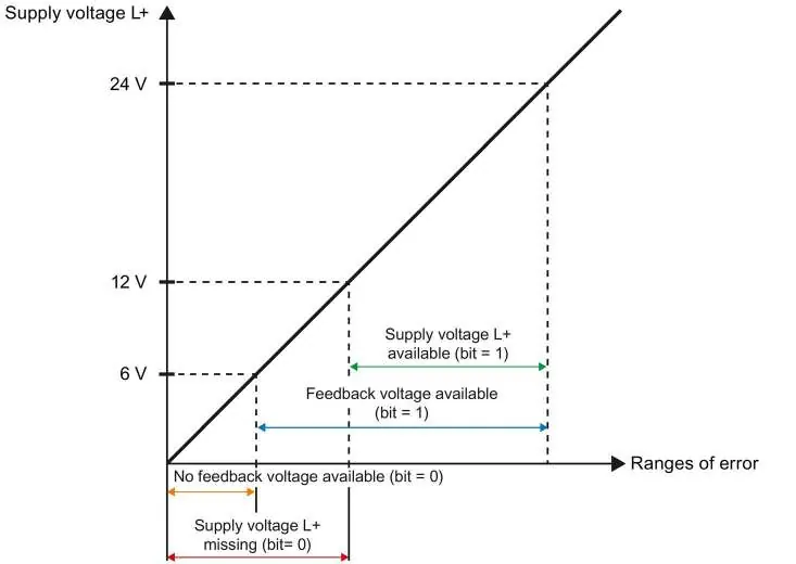
The server module allows you to read out the status of the supply voltage L+ and the feedback voltage of I/O modules. The length of the input data depends on the configuration of the CPU/interface module:
- Interface module with 12 I/O modules: 2/4 bytes.
- Interface module with 32 I/O modules: 4/8 bytes.
- CPU/interface module with 64 I/O modules: 8/16 bytes.
The input data provides bit-level status for each slot, indicating whether the supply voltage L+ is present or missing, and whether the feedback voltage is present or missing.
Diagnostics and troubleshooting
The module outputs diagnostics alarms for specific events, which can be read out in the diagnostics buffer of the CPU. If you encounter an error code 1BH, it indicates an invalid firmware version (< V1.1.1). The solution is to replace the server module or perform a firmware update.
Technical specifications
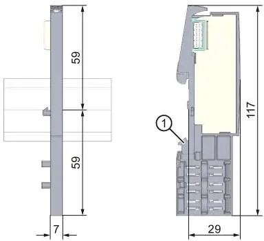
- Dimensions (W x H x D): 7 mm x 117 mm x 36 mm
- Weight: Approx. 19 g
Manufacturer information
Siemens AG
Practical help
Common problems
Server module with invalid firmware version (< V1.1.1)
Replace the server module or perform a firmware update.
Missing supply voltage L+
Check the input data bits; bit 0 indicates missing voltage or module.
Before use
- Ensure all I/O modules are inserted (no empty slots).
- Verify firmware version is at least V1.1.1.
- Configure the module using STEP 7 (TIA Portal) or a GSD file.
- Ensure the module is properly seated on the backplane bus.
Images and diagrams
- The manual includes diagrams for input data mapping based on the number of I/O modules (12, 32, or 64).
- Dimensional drawings show the module's physical footprint and mounting rail contact.
Model compatibility
- Compatible with ET 200SP distributed I/O system.
- Supports IM 155-6 PN BA interface module.

Manual page author
Michael Turner
Technical manual editor
Reviews PDF manuals for structure, safety notes, and practical product details so readers can find the right information quickly.