Industrial / I/O Modules
Equipment Manual for Siemens SIMATIC ET 200SP HA F-AI 8xI 2-/4-wire HART HA
Comprehensive equipment manual for the Siemens SIMATIC ET 200SP HA F-AI 8xI 2-/4-wire HART HA module. Includes installation, wiring, configuration, safety parameters, and diagnostic information.
Quick answers from the manual
Quick answer
- The F-AI 8xI 2-/4-wire HART HA is a fail-safe analog input module for the SIMATIC ET 200SP HA system, supporting 8 current inputs and HART communication. p. 11
Key actions
- Wiring the module p. 17, 40, 44
- Configuring parameters p. 23, 24
First start
- Ensure the module is properly configured in S7 F-Systems and the supply voltage is connected. p. 18, 21
Problems and fixes
Wire break
Check sensor wiring or disable diagnostics.
p. 67
Overtemperature
Operate within specified temperature range.
p. 67Maintenance and reset
- After fault correction, you must reintegrate the F-module in the safety program. p. 67
Technical specifications
| Parameter | Value | Meaning | Pages |
|---|---|---|---|
| Number of analog inputs | 8 | For current measurement | p. 90 |
| Input resistance | 150 Ohm | For 0-20mA and 4-20mA | p. 90 |
Where to find it in the PDF
- Product Overview p. 11
- Connection p. 15
- Technical Specifications p. 89
Table of contents
Manual images
Click an image to enlargeQuick guide from the manual
This manual provides essential information for the installation, configuration, and operation of the Siemens SIMATIC ET 200SP HA F-AI 8xI 2-/4-wire HART HA module (6DL1136-6AA00-0PH1). This fail-safe analog input module supports 8 current inputs and HART communication. Ensure you use the correct terminal block for your application and configure the module using S7 F-Systems V6.4 or higher.
Product overview
The F-AI 8xI 2-/4-wire HART HA is a fail-safe analog input module designed for process control. Key features include:
- 8 fail-safe analog inputs (up to SIL3/Cat.3/PLd or SIL3/Cat.4/PLe with CPU voting).
- Measuring ranges: 0 to 20 mA and 4 to 20 mA.
- HART communication support (Rev. 5 to Rev. 7).
- Configurable diagnostics and maintenance messages.
- Support for IO redundancy.
Connection and wiring
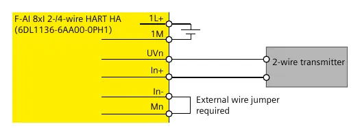
The module requires specific terminal blocks for operation. Terminal blocks are not included and must be ordered separately. Wiring depends on the application case (2-wire or 4-wire transmitter). Always use shielded cables to ensure installation free of interference voltage.
Configuration
Configuration is performed in HW Config using S7 F-Systems V6.4 or higher. Parameters include:
- F-parameters: F_source_address, F_destination_address, F_monitoring time.
- Cross-channel parameters: Measurement type, measuring range, smoothing, and diagnostics settings.
- HART parameters: HART gate, HART activated, and message frame repetitions.
Applications
The module supports various application cases to achieve specific safety requirements (SIL/Cat./PL). These include 1oo1, 1oo2, and 2oo3 evaluations. Refer to the specific application case sections in the manual for detailed wiring diagrams and parameter settings.
Diagnostics and maintenance
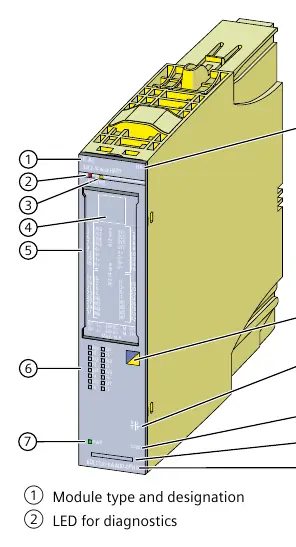
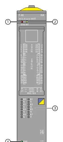
The module provides comprehensive diagnostic information via LEDs and diagnostic interrupts. Common diagnostic messages include:
- Overtemperature: Ensure operation within the specified temperature range.
- Wire break: Check sensor wiring or disable diagnostics if not required.
- Supply voltage missing: Verify the supply voltage at the terminal block.
Maintenance events are indicated by the MT LED. All HART diagnostics are also reported as maintenance events.
Technical specifications
The module operates on 24 V DC. It features 8 analog inputs for current measurement with a destruction limit of 35 mA. The input resistance is 150 Ohm. The module dimensions are 22.5 mm (W) x 115 mm (H) x 138 mm (D), with an approximate weight of 220 g.
Manufacturer information
Siemens AG
Practical help
Common problems
Wire break detected
Check sensor wiring, ensure cable cross-section is sufficient, or disable diagnostics if not needed.
HART communication error
Check process wiring, verify parameter assignment, ensure current is >= 4mA.
Module not configured
Ensure correct configuration in HW Config using S7 F-Systems V6.4 or higher.
Before use
- Verify the module article number (6DL1136-6AA00-0PH1).
- Ensure power supply is 24V DC with safe electrical isolation.
- Select the appropriate terminal block (e.g., light gray for new potential group).
- Use shielded cables for installation.
- Configure the module in S7 F-Systems V6.4 or higher.
Specs in practice
- SIL3/Cat.3/PLd
- Safety Integrity Level 3 / Category 3 / Performance Level d (safety rating).
Images and diagrams
- Wiring schemes show connections for 2-wire and 4-wire transmitters.
- Block diagrams illustrate the internal signal path and HART modem integration.
Model compatibility
- Requires S7 F-Systems V6.4 or higher for configuration.
- IO redundancy requires TB45R-P32 terminal block (6DL1193-6TP00-0DF1).

Manual page author
Emily Carter
User documentation editor
Prepares concise manual descriptions and highlights the most useful setup, operation, and maintenance information for readers.