Industrial / I/O Modules
Product Information for Siemens ET 200SP Distributed I/O System
Comprehensive product information and technical guide for the Siemens ET 200SP distributed I/O system. Includes module compatibility, wiring diagrams, climatic conditions, and configuration notes.
Table of contents
Manual images
Click an image to enlargeQuick guide from the manual
This document serves as a product information supplement for the Siemens ET 200SP distributed I/O system. It provides essential data regarding module combinations, technical specifications, and configuration requirements that supersede information in standard system manuals.
Module Overview
The ET 200SP system supports a wide range of modules, including CPUs, interface modules, BaseUnits, I/O modules, and motor starters. Compatibility between BaseUnits and I/O modules is critical; refer to the compatibility tables in the manual to ensure correct hardware selection. Accessories such as BusAdapters, labeling strips, and mounting rails are also available to complete the installation.
Installation and Wiring
Proper installation is required for safe operation. Observe the following climatic conditions:
- Temperature: 0 °C to 60 °C (horizontal mounting), 0 °C to 50 °C (vertical mounting).
- Relative humidity: 10% to 95% (without condensation or icing).
- Air pressure: 1140 hPa to 795 hPa (corresponds to -1000 m to 2000 m altitude).
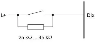
For operation at altitudes above 2000 m, apply derating factors to the maximum ambient temperature. Wiring diagrams are provided for various configurations, including 2-wire and 3-wire connections. For digital input modules with wire-break detection, a parallel resistor (25 kΩ to 45 kΩ) is required when using mechanical encoder contacts.
Configuration and Compatibility
Always verify the firmware version of your modules and the required STEP 7 (TIA Portal) version before configuration. Some modules require specific hardware function statuses (FS) or firmware versions for proper operation. If a compilation error occurs in isochronous mode, update the module description in the network or device view.
Technical Specifications
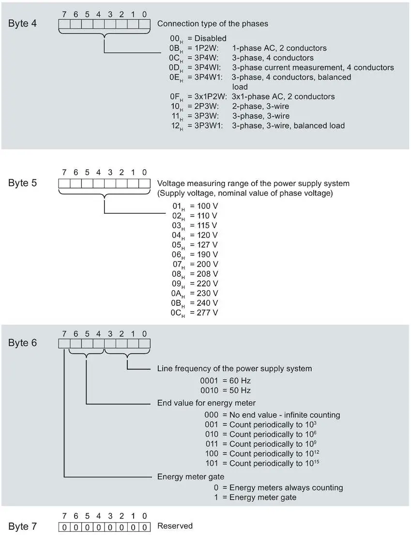
The system supports various communication protocols and configurations. For energy meters, ensure correct association of measured variables and IDs. The backplane bus cycle time is determined by the configured update time, with a minimum of 1 ms.
Manufacturer information
Siemens AG
Practical help
Common problems
Compilation error in isochronous mode (e.g., 'The specific Ti value is invalid')
Upgrade the module description in the network or device view using the 'Update module description' function.
Wire-break detection not working with mechanical encoder contacts
Connect a 25 kΩ to 45 kΩ resistor in parallel to each mechanical encoder contact.
Module failure or unexpected behavior at high altitudes (> 2000 m)
Apply derating factors to the maximum ambient temperature and ensure power supplies are rated for high altitudes.
Before use
- Verify module compatibility with the selected BaseUnit.
- Check the required firmware version for your specific module.
- Ensure the STEP 7 (TIA Portal) version supports the module.
- Verify that power supplies are rated for the operating altitude.
- Check climatic conditions (temperature, humidity, air pressure) against specifications.
Specs in practice
- Derating factor
- A multiplier used to reduce the maximum permissible ambient temperature for operation at altitudes above 2000 m.
- Backplane bus cycle time
- The time required for the interface module to output new data and read new input data; minimum is 1 ms.
Images and diagrams
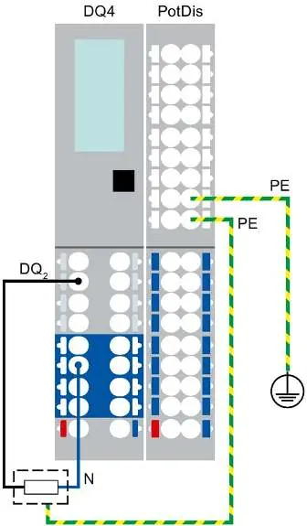
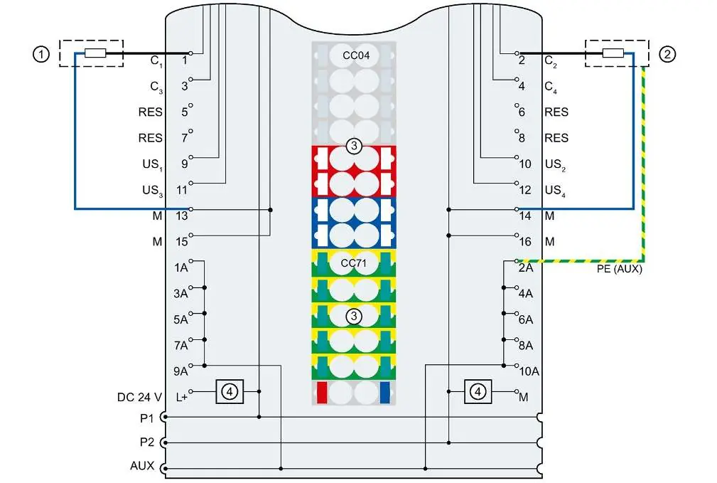
- Wiring diagrams illustrate 2-wire and 3-wire connections for digital and analog modules.
- Terminal labeling diagrams show unique numbering per slot for PotDis-TB and PotDis-BU.
Model compatibility
- Some modules require specific firmware versions for operation with certain interface modules.
- Energy Meter modules have specific slot requirements on the ET 200SP.

Manual page author
David Miller
Documentation analyst
Organizes user manual content into clear summaries, with attention to model details, product context, and everyday usability.