Plumbing / Valves & Fittings
Sloan B-15-A Push Button Repair and Maintenance Guide
A comprehensive repair and maintenance guide for Sloan B-15-A push buttons, including exploded views, parts lists, and wall thickness dimension charts for exposed and concealed models.
Table of contents
Manual images
Click an image to enlargeImportant Information
This document serves as a repair and maintenance guide for various Sloan push button assemblies, including Push, Pull, Pedal Push, and Pedal Handle Push Buttons for Royal and Crown series. It provides exploded views, parts lists, and specific dimension charts for wall thickness installation. Always verify if your specific assembly is marked as obsolete before ordering parts.
Overview of Push Button Assemblies
The guide covers several configurations of push buttons:
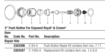
- 3" Push Button: Available for both Exposed and Concealed Royal and Crown installations.
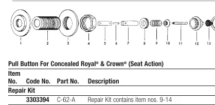
- Pull Button: Designed for Exposed and Concealed Royal and Crown (Seat Action) installations.
- Pedal Push Button: Available for Exposed and Concealed Royal and Crown installations.
- Pedal Handle Push Button: Available for Exposed and Concealed Royal and Crown installations.
Repair Kits and Parts
Each assembly type has specific repair kits containing essential components like seals, springs, plungers, and bushings. When performing maintenance:
- Identify the specific assembly type (Exposed vs. Concealed).
- Refer to the corresponding parts list to find the correct Code No. and Part No.
- Note that some parts are only available within a repair kit.
- Consult the factory for assemblies or parts marked as obsolete or where specific lengths are required.
Wall Thickness and "L" Dimension
For concealed installations, the "L" dimension is critical for proper fitment. Use the provided ID chart to determine the correct filler rod and socket assembly based on your wall thickness.
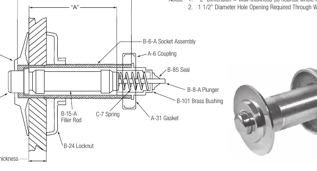
- "L" Dimension Calculation: Wall thickness (to the nearest whole inch) + 2 3/4 inches.
- Installation Requirement: A 1 1/2-inch diameter hole opening is required through the wall.
Maintenance Notes
Regular maintenance involves checking the plunger, spring, and seal. If the button is not functioning correctly, inspect these components for wear. Ensure the correct wall flange and coupling are used for your specific installation type (e.g., Wall Box Installation).
Practical help
Common problems
Button not functioning or leaking
Inspect the plunger, spring, and seal. Replace worn components using the specific repair kit listed for your assembly type.
Wall thickness mismatch
Use the 'L' Dimension Chart to verify the correct filler rod (B-15-A) and socket assembly (B-6-A) for your specific wall thickness.
Part is obsolete
Some assemblies (e.g., Pedal Handle PB) are marked as obsolete. Consult the factory for replacement options or compatible alternatives.
Before use
- Identify if your unit is Exposed or Concealed.
- Determine if it is a Push, Pull, or Pedal type.
- Measure the wall thickness to calculate the required 'L' dimension.
- Verify the assembly series (Royal or Crown).
- Check the parts list for the correct repair kit number.
Specs in practice
- Wall Box Installation
- A specific installation method requiring an in-wall sleeve (B-6/B-6-A) and specific flange types.
Images and diagrams
- Exploded views illustrate the correct order of assembly for plungers, springs, and seals.
- The 'L' Dimension chart diagram shows how to measure wall thickness relative to the socket assembly and filler rod.
Model compatibility
- Parts are specific to Royal and Crown series.
- Some assemblies are marked as OBSOLETE.
- Wall box installation requires specific components (e.g., B-6/B-6-A sleeve).

Manual page author
Michael Turner
Technical manual editor
Reviews PDF manuals for structure, safety notes, and practical product details so readers can find the right information quickly.