Lighting / Fixtures
Sunco CN_NC6-1PK 6-inch New Construction Can Installation Guide
Installation guide for Sunco 6-inch New Construction Cans. Includes step-by-step mounting instructions for joist and drop ceilings, wiring diagrams, and technical specifications.
Quick answers from the manual
Quick answer
- The Sunco CN_NC6-1PK is a 6-inch new construction can light housing. Installation involves mounting the bar hangers to joists or a drop ceiling grid, wiring the junction box, and securing the housing. For retrofit applications, a 6.3-inch hole is required. p. 1, 2
Key actions
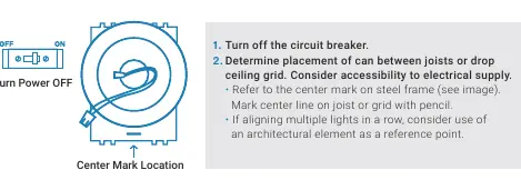
- Turn off the circuit breaker before starting installation. p. 1
- Connect wires: Live (black), Neutral (white), and Ground (yellow/green). p. 2
First start
- Turn on the circuit breaker and test the light after installation is complete. p. 2
Maintenance and reset
- Regularly clean the light panel to ensure efficient light. Do not use harsh solvents. p. 1
Technical specifications
| Parameter | Value | Meaning | Pages |
|---|---|---|---|
| Voltage | 120/277V | Operating voltage range | p. 2 |
| Max Wattage | 24W | Maximum power consumption | p. 2 |
Where to find it in the PDF
- Installation Guide p. 1, 2
Table of contents
Manual images
Click an image to enlargeQuick Guide
This document provides installation instructions for the Sunco 6-inch New Construction Can. Before starting, ensure the power is turned off at the circuit breaker. The fixture is compatible with insulated ceilings (type IC and type-T) and suspended ceilings (type-S). Always verify the product for shipping damage before installation.
Required Tools
- Ladder
- Hammer
- Wire Clippers/Strippers
- Pliers
- Flathead Screwdriver
- Pencil
- Compass
- Tape Measure
- Drywall Saw
Installation
1. Preparation: Turn off the circuit breaker. Determine the placement of the can between joists or in the drop ceiling grid. Use the center mark on the steel frame to mark the center line on the joist or grid with a pencil.
2. Mounting: Bar hangers come pre-inserted on the steel frame. Adjust them to fit your ceiling structure:
- Joist Ceiling: Extend bar hangers to fit between joists. The hanger bar flange should be level with the bottom of the joist. Secure temporarily by hammering pre-installed nails into the joists.
- Suspended/Drop Ceilings: Extend bar hangers 1 inch past the T-bars, rest the fixture on the T-bars, and secure with wire.
3. Positioning: Slide the housing along the hangers to align the housing center mark with your pencil mark. Secure the housing by tightening the indicated screw. If using joists, drive the nails in fully.
Wiring
1. Junction Box: Open the junction box by releasing the clamp and removing a knockout. Feed supply wires through the knockout.
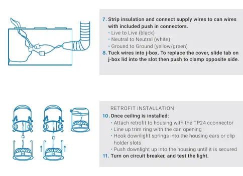
2. Connections: Strip insulation and connect supply wires to the can wires using the included push-in connectors:
- Live: Black to Black
- Neutral: White to White
- Ground: Yellow/Green to Yellow/Green
3. Closing: Tuck wires into the junction box. Replace the cover by sliding the tab on the lid into the slot, then push to clamp the opposite side.
Retrofit Installation
If installing after the ceiling is finished:
- Use a compass and the can's center mark to determine hole placement.
- Cut a 6.3-inch diameter hole in the ceiling using a drywall saw.
- Attach the retrofit to the housing with the TP24 connector.
- Line up the trim ring with the can opening.
- Hook downlight springs into the housing ears or clip holder slots.
- Push the downlight up into the housing until secured.
- Turn on the circuit breaker and test the light.
Specifications
- Voltage: 120/277V
- Max Wattage: 24W
- Retrofit Size: 6-inch diameter
- Hanger Adjustment Range: 13-5/8 to 25 inches
- Operating Temperature: Max 194°F
- Suitable Locations: Wet & Damp
- Weight: 1lb 13oz
- Warranty: 5 years
Practical help
Common problems
Fixture not fitting between joists
Adjust the pre-inserted bar hangers to fit the specific spacing of your joists.
Difficulty securing housing
Ensure the housing is aligned with the center mark and the indicated screw is tightened securely.
Wiring connection issues
Ensure wires are stripped correctly and fully inserted into the push-in connectors (Live to Black, Neutral to White, Ground to Green).
Before use
- Turn off the circuit breaker.
- Check the product for any damage sustained during shipping.
- Gather all required tools (ladder, wire strippers, drywall saw, etc.).
- Verify ceiling type (IC, type-T, or type-S) compatibility.
- Wear safety eyeglasses and gloves.
Specs in practice
- 6.3 inch hole
- The required diameter for the ceiling cutout when performing a retrofit installation.
Images and diagrams
- The wiring diagram illustrates the junction box access and the color-coded wire connections (Black to Black, White to White, Green to Green).
- Installation diagrams show the difference between Joist Ceiling mounting (using nails) and Drop Ceiling mounting (using wire).
Model compatibility
- Compatible with insulated ceilings (type IC and type-T).
- Compatible with suspended ceilings (type-S).

Manual page author
David Miller
Documentation analyst
Organizes user manual content into clear summaries, with attention to model details, product context, and everyday usability.