Electronics / Speakers & Soundbars
Quick Start Guide for Tannoy CMS 1201DCT and CMS 1201DC Ceiling Loudspeaker
Get started with your Tannoy CMS 1201DCT or CMS 1201DC ceiling loudspeaker. This guide covers installation methods, wiring, transformer settings, and technical specifications.
Table of contents
Manual images
Click an image to enlargeQuick guide from the manual
The Tannoy CMS 1201DC and CMS 1201DCT are large-format ceiling loudspeakers designed for distributed sound applications. Before installation, inspect the product for any transit damage. Ensure that the installation method complies with local safety standards and regulations, as requirements for flying or hanging equipment vary by country.
Product Overview
The system consists of three discrete components:
- Loudspeaker assembly: Includes a Dual Concentric drive unit mounted on a ported steel baffle and crossover. The DCT model includes a line transformer.
- Steel back-can: Features multiple mounting points.
- Grille assembly: Includes a moulded bevel cover.
Installation Guide
The back-can is designed for versatility and can be installed using several methods:
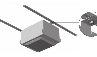
Unistrut Roof Rail System
Steel mounting lugs allow for fitting to a Unistrut roof rail system. Configurations can be direct or via secondary prefixed cross struts. Use a large series washer at the fixing point to help spread the load.
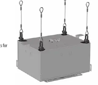
Flying using Eyebolts
The device can be hung via 4 top-mounted eye bolts. The rear of the back-can has mounting points for both M10 and 3/8 UNC threaded eyebolts.
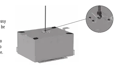
Flying using Screwed Rod
The design supports a single-point central hang via M10 or 3/8 UNC threaded rod, utilizing the slotted mounting saddle on the top of the back-can. If required, a safety wire can be attached to any of the M10 flying points.
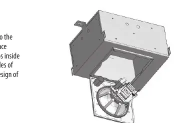
Fitting the Loudspeaker Assembly
One edge of the baffle clips onto the steel box to hold it in place while the installer secures the assembly. Connection is made via terminal barrier strips inside the can, accessible via conduit knockouts on all five sides.
Wiring and Setting Up
The CMS 1201DC is a low-impedance variant, while the CMS 1201DCt includes a line transformer for 70 V or 100 V distributed lines. Transformer tappings must be configured before screwing the driver assembly into the back-can:
- 70 V systems: 60 W / 30 W / 15 W / 7.5 W / OFF
- 100 V systems: 60 W / 30 W / 15 W / OFF
If level adjustment is required later, the baffle can be hung from the can via a hinged edge, allowing hands-free adjustment.
Technical Specifications
- Frequency Response (-3 dB): 60 Hz - 20 kHz
- Nominal Coverage Angle: 90 Degrees Conical
- Nominal Impedance: 8 Ohms
- Power Handling (Average/Programme/Peak): 200 W / 400 W / 800 W
- Dimensions (H x W x D): 331 x 725 x 516 mm
Practical help
Common problems
Unit damaged during transit
Notify your dealer immediately and retain the shipping carton for inspection.
Need to adjust transformer settings after installation
The baffle can be hung from the can via a hinged edge, leaving both hands free to make the required adjustments.
Before use
- Inspect the product for transit damage upon unpacking.
- Verify the installation surface can support the weight of the unit.
- Consult local safety standards for flying/hanging requirements.
- Ensure the correct mains voltage is used for your specific model.
- Configure transformer taps (for 1201DCt) before final assembly.
Specs in practice
- Transformer Taps
- Settings for 70V or 100V distributed lines (60W/30W/15W/7.5W).
- Nominal Impedance
- 8 Ohms for the standard low-impedance variant.
- Coverage Angle
- 90 degrees conical, providing uniform response.
Images and diagrams
- Installation diagrams illustrate mounting via Unistrut, eyebolts, and threaded rods.
- Dimensions diagram provides detailed measurements for mounting and installation planning.
Model compatibility
- CMS 1201DC is the standard low-impedance variant.
- CMS 1201DCt is the line transformer-equipped version for 70V/100V lines.

Manual page author
David Miller
Documentation analyst
Organizes user manual content into clear summaries, with attention to model details, product context, and everyday usability.