Electronics / Speakers & Soundbars
User Manual for Tannoy CMS 1201SW Ceiling Subwoofer
Quick start guide and installation manual for the Tannoy CMS 1201SW 12-inch ceiling subwoofer. Includes mounting instructions for Unistrut rails, eyebolts, and screwed rods, plus technical specifications.
Table of contents
Manual images
Click an image to enlargeQuick guide from the manual
The Tannoy CMS 1201SW is a 12-inch large-format in-ceiling subwoofer designed for installation applications. This guide covers the unpacking, installation, and safety procedures required for setting up the system. Ensure all electrical, mechanical, and acoustic considerations are discussed with qualified personnel before installation.
Product Overview
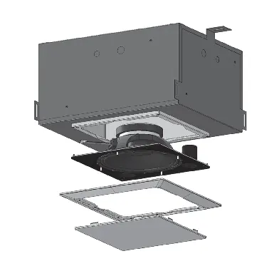
The system consists of three discrete components that are ordered separately:
- Loudspeaker assembly: Includes the drive unit mounted on a ported steel baffle.
- Steel back-can: Features multiple mounting points and internal damping.
- Grille assembly: Includes a moulded bevel cover.
Installation Guide
The back-can is designed for versatility and can be installed using several methods:
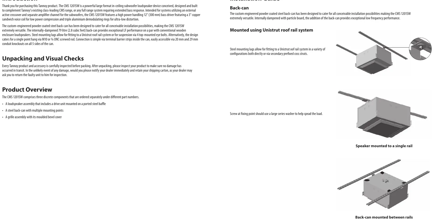
Mounted using Unistrut roof rail system
Steel mounting lugs allow for fitting to a Unistrut roof rail system in various configurations, either directly or via secondary prefixed cross struts. Use a large series washer at the fixing point to help spread the load.
Flying using Eyebolts
The system can be suspended via four top-mounted eye bolts. Ensure the area underneath the product is free of human traffic and that the system is installed by qualified personnel.
Flying using Screwed Rod
The design supports a single-point central hang via an M10 or 3/8 UNC screwed rod, utilizing the slotted mounting saddle on the top of the back-can. To install, run a nut 50 mm (2") up the rod, followed by two plain washers and a locking nut (Nyloc). Hook the back-can onto the rod between the washers.
Fitting the loudspeaker assembly
Mounting the loudspeaker assembly to the pre-installed back-can is a one-person job. One edge of the baffle clips onto the steel box to hold it in place while the installer secures the assembly. Connections are made via terminal barrier strips inside the can, accessible via 20 mm and 29 mm conduit knockouts.
Specifications
- Driver: 12" (300 mm) bass driver with 3" copper sandwich voice coil.
- Back-can volume: 79 litres (2.8 cubic feet).
- Power handling: 400 W (Average), 800 W (Programme), 1600 W (Peak).
- Recommended amplifier power: 800 W @ 8 Ohms.
- Nominal impedance: 8 Ohms.
- Dimensions: 331 x 725 x 516 mm.
Safety Instructions
Important: Always follow local safety regulations. Do not install in confined spaces like bookshelves. Keep the apparatus away from heat sources, water, and naked flames. Ensure the unit is connected to a mains socket with a protective earthing connection.
Practical help
Common problems
System installation or flying appears unstable
Ensure installation is performed by qualified and certified personnel using dedicated equipment. Conduct regular checks to ensure the system remains secure.
Difficulty fitting the back-can to the screwed rod
Ensure the nut has cleared the guide slot on the mounting saddle before locking the top nut down to secure.
Before use
- Inspect the product and accessories for transit damage immediately after unpacking.
- Retain the shipping carton if damage is found, as the dealer may require it for inspection.
- Verify that the mounting surface and chosen installation method (Unistrut, eyebolts, or rod) are appropriate for the weight.
- Ensure all electrical, mechanical, and acoustic considerations are discussed with qualified personnel.
- Check that the mains voltage is correct for your specific model before connecting.
Specs in practice
- Power Handling (Programme)
- 800 W; the recommended power capacity for the amplifier channel.
- Nominal Impedance
- 8 Ohms; ensure your amplifier is compatible with this load.
- Back-can Volume
- 79 litres; provides the acoustic enclosure for the subwoofer.
Images and diagrams
- Unistrut mounting: Shows the back-can attached to rails with cross struts.
- Eyebolt flying: Illustrates the four-point suspension method.
- Screwed rod mounting: Details the nut and washer arrangement on the rod.
- Loudspeaker assembly: Shows the baffle clipping into the back-can.
- Grille fitting: Shows the final assembly step.
Model compatibility
- Requires an external active crossover and separate amplifier channel.
- Compatible with Unistrut roof rail systems.
- Supports M10 or 3/8 UNC screwed rod for single-point suspension.

Manual page author
David Miller
Documentation analyst
Organizes user manual content into clear summaries, with attention to model details, product context, and everyday usability.