Electronics / Speakers & Soundbars
User Manual for Tannoy CMS 1201DCT and CMS 1201DC Ceiling Loudspeaker
Quick start guide for the Tannoy CMS 1201DCT and CMS 1201DC ceiling loudspeakers. Includes installation instructions for Unistrut, eyebolts, and threaded rods, plus wiring and transformer settings.
Table of contents
Manual images
Click an image to enlargeQuick Guide
The Tannoy CMS 1201DC and CMS 1201DCT are large-format in-ceiling loudspeakers designed for high-ceiling installations such as ballrooms, shopping malls, and sports halls. The system consists of three main components: the loudspeaker assembly, a steel back-can, and a grille assembly.
Product Overview
The system comprises three discrete components:
- Loudspeaker assembly: Includes a Dual Concentric drive unit mounted on a ported steel baffle and a crossover. The DCT model includes a line transformer.
- Steel back-can: Features multiple mounting points and is internally dampened with OSB2 board for low-frequency performance.
- Grille assembly: Includes a moulded bevel cover.
Installation Guide
Mounting Options
The back-can is designed for versatility with several mounting methods:
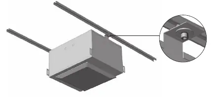
- Unistrut roof rail system: Steel mounting lugs allow for direct fitting or via secondary prefixed cross struts. Use a large series washer at the fixing point to distribute the load.
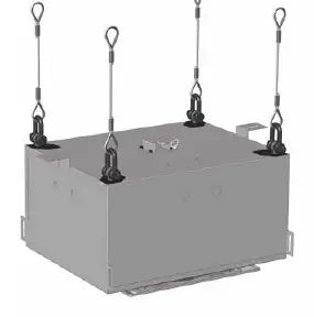
- Eyebolts: The rear of the back-can has mounting points for M10 and 3/8 UNC threaded eyebolts for suspension.
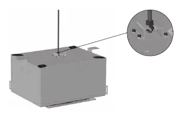
- Screwed Rod: Supports single-point central hanging via M10 or 3/8 UNC threaded rod using the slotted mounting saddle on top of the back-can.
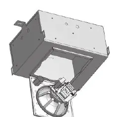
Fitting the Loudspeaker Assembly
Mounting the assembly to the pre-installed back-can is a one-person job. One edge of the baffle clips onto the steel box to hold it in place while the installer secures the assembly. Connections are made via terminal barrier strips inside the can, accessible through 20 mm and 29 mm conduit knockouts on all five sides.
Fitting the Grille
Once the loudspeaker assembly is secured, attach the grille assembly with its moulded bevel cover to complete the installation.
Wiring and Setting Up
The CMS 1201 is available in a low-impedance variant (CMS 1201DC) and a transformer-equipped version (CMS 1201DCT) for 70 V or 100 V distributed lines. Transformer tappings must be configured before screwing the driver assembly into the back-can:
- 70 V systems: 60 W / 30 W / 15 W / 7.5 W / OFF
- 100 V systems: 60 W / 30 W / 15 W / OFF
If level adjustment is required later, the baffle can be hung from the can via a hinged edge, allowing for hands-free adjustment.
Technical Specifications
- Frequency response (-3 dB): 60 Hz - 20 kHz
- Nominal Coverage Angle: 90 Degrees Conical
- Power Handling (Average/Programme/Peak): 200 W / 400 W / 800 W
- Nominal Impedance: 8 Ohms
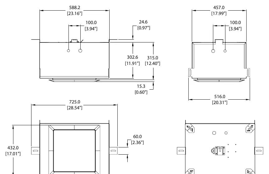
- Dimensions (H x W x D): 331 x 725 x 516 mm
Safety Information
Always consult local safety standards and regulations before installing overhead equipment. Ensure the mounting surface can support the weight of the loudspeaker. Use only high-quality professional speaker cables with 1/4" TS or twist-locking plugs. Repairs must be performed by qualified service personnel only.
Practical help
Common problems
Low frequency performance issues
Ensure the back-can is properly installed and dampened with the provided OSB2 board.
Transformer settings incorrect
Configure transformer taps before screwing the driver assembly into the back-can.
Before use
- Inspect the product for transit damage upon unpacking.
- Verify the mounting surface can support the loudspeaker weight.
- Check local safety regulations for overhead installation.
- Ensure the correct mains voltage/amplifier output for your model.
- Configure transformer taps (if using DCT model) before final assembly.
Specs in practice
- Frequency response
- The range of sound frequencies the speaker can reproduce (60 Hz - 20 kHz).
- Transformer Taps
- Power settings for 70V/100V distributed lines; allows adjusting volume/power per speaker.
- Nominal Impedance
- The electrical resistance (8 Ohms) for the low-impedance variant.
Images and diagrams
- Installation diagrams show mounting via Unistrut rails, eyebolts, and threaded rods.
- The loudspeaker assembly hooks onto the back-can for easy installation.
Model compatibility
- CMS 1201DC is a low-impedance variant.
- CMS 1201DCT includes a 60W line transformer for 70V/100V lines.

Manual page author
Emily Carter
User documentation editor
Prepares concise manual descriptions and highlights the most useful setup, operation, and maintenance information for readers.