HVAC / Packaged Rooftop Units
Temperzone OPA 1410RLTM4FPQD Econex Pro HVAC Technical Manual
Technical manual for the Temperzone OPA 1410RLTM4FPQD Econex Pro HVAC unit. Includes detailed wiring schematics, installation dimensions, electrical specifications, sensor connections, and DIP switch settings for installers.
Table of contents
Manual images
Click an image to enlargeImportant Information
This document provides technical specifications, installation dimensions, and wiring schematics for the Temperzone OPA 1410RLTM4FPQD Econex Pro HVAC unit. It is intended for qualified installers and technicians. Ensure all electrical work complies with local regulations and the provided wiring diagrams.
Specifications
The unit features the following key technical parameters:
- Refrigerant: R32 (7.1 kg/sys).
- Compressor: Inverter scroll (x4).
- Power Supply: 3 ph. 400V AC 50Hz + N + E.
- Nominal Air Flow: 8100 l/s.
- Max Running Amps: 116 / 111 / 121 A (depending on configuration).
- Indoor Fan Motor: EC Plug 3.65kW (x4).
- Compressor Circuit Breaker: 50 A (x4).
Dimensions and Clearances
The unit requires specific clearances for maintenance and airflow:
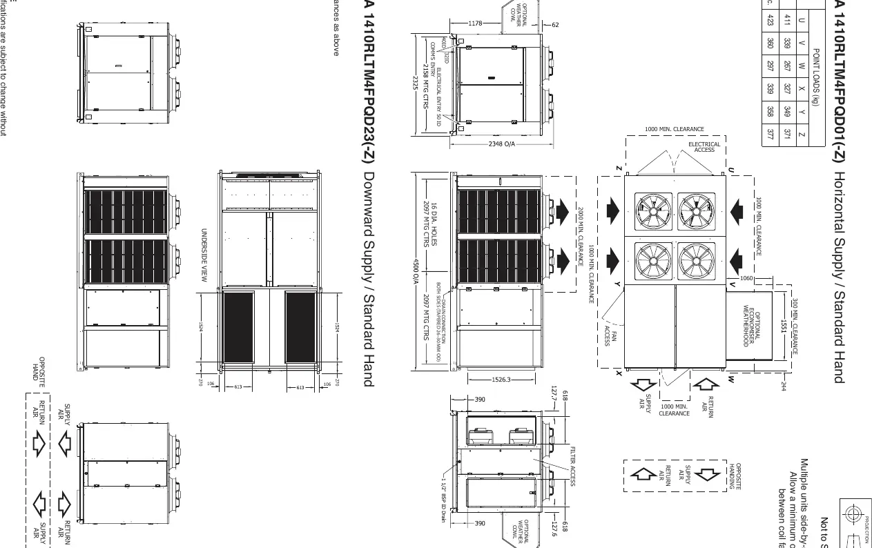
- Minimum Clearances: Maintain at least 1000mm clearance around the unit for electrical and fan access.
- Side-by-side installation: Allow a minimum of 2m between coil faces.
- Drain Connection: Tapered 26–30 mm OD on both sides.
Wiring and Electrical Connections
The manual contains detailed wiring schematics for systems 1 through 4, including:
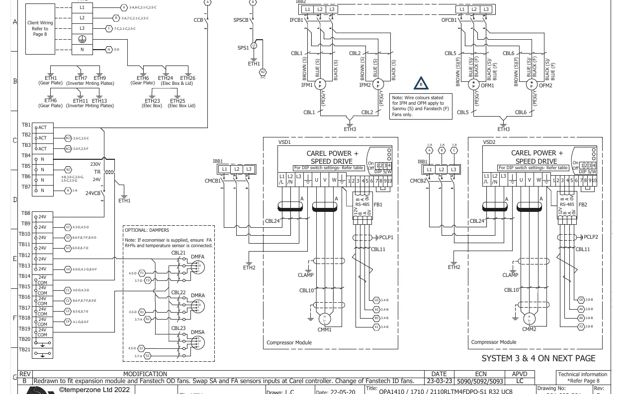
- Client Wiring: Refer to the terminal block (MTB) connections for external protection and isolator switches.
- Fan Connections: Wiring varies based on the manufacturer (Sanmu, Fanstech, EBM, or Rosenberg). Ensure the correct schematic is followed for the installed fan type.
- Control Circuit: Requires 24-hour power on L1 for the control circuit and crankcase heaters.
- Modbus Addresses: UC8 (44-47), VSD (10), IFM (21-24), OFM (31-34).
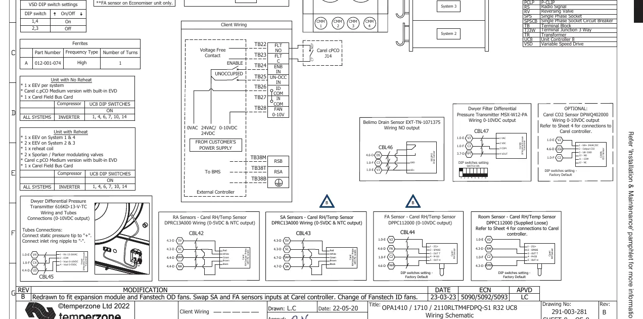
Sensor and DIP Switch Configuration
Proper configuration is required for sensors and system operation:
- Sensors: Supports various sensors including Room Air, Return Air, Supply Air, and Fresh Air (RH% & Temp). Ensure correct wiring polarity and sensor type (NTC or 0-10V).
- DIP Switch Settings: Specific settings are required for the UC8 controller depending on whether the unit has reheat functionality.
- Optional Sensors: If an economiser is supplied, ensure the FA RH% and temperature sensor are connected.
Practical help
Common problems
Unit fails to start
Verify 24-hour power is supplied to L1 for the control circuit and crankcase heaters.
Communication error between components
Check Modbus addresses: UC8 (44-47), VSD (10), IFM (21-24), OFM (31-34).
Incorrect sensor readings
Verify sensor type (NTC/0-10V) and ensure wiring matches the specific sensor schematic (e.g., RA, SA, FA sensors).
Before use
- Verify power supply is 3 ph. 400V AC 50Hz + N + E.
- Ensure minimum 1000mm clearance around the unit.
- Check that RCD type B, 30mA, 3 pole is installed.
- Confirm fan type (Sanmu, Fanstech, EBM, Rosenberg) and use the corresponding wiring diagram.
- Ensure 24-hour power is connected to L1.
Specs in practice
- Refrigerant Charge
- 7.1 kg of R32 per system.
- Max. ext. static pressure
- 120 Pa at 12,100 l/s.
- Compressor oil type
- POE-46 (NXG5020 or equivalent).
Images and diagrams
- Wiring Schematics: Detailed diagrams for System 1-4, fan connections, and client wiring.
- Dimensions: Layouts for Horizontal and Downward supply configurations.
Model compatibility
- Economiser: Requires FA RH% and temperature sensor connection.
- Fan Connections: Wiring varies by manufacturer; refer to the specific sheet for Sanmu, Fanstech, EBM, or Rosenberg fans.

Manual page author
David Miller
Documentation analyst
Organizes user manual content into clear summaries, with attention to model details, product context, and everyday usability.