HVAC / Air Conditioners
Installation and Maintenance Manual for Temperzone ISD 135K, 160K, 200K, 230K Ducted Split System Indoor Units
Comprehensive installation and maintenance guide for Temperzone ISD 135K, 160K, 200K, and 230K ducted split system indoor units. Includes mounting instructions, condensate drain setup, wiring diagrams, and maintenance schedules.
Table of contents
Manual images
Click an image to enlargeImportant Information from the Manual
This document provides installation and maintenance instructions for the Temperzone ISD 135K, 160K, 200K, and 230K ducted split system indoor units. These units are designed to be coupled with specific OSA outdoor units. Installation must comply with all national and local safety codes. The unit is designed for use ONLY with HFC-410A (R410A) refrigerant.
Installation and Mounting
The unit should be mounted using the optional spring mounting system to minimize vibration transfer. If a more rigid installation is required, use four threaded rods (not supplied) with the 'L' shaped brackets provided on the unit. The unit features a built-in sloping drain tray, so it must be mounted level.
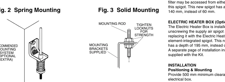
- Clearance: Provide a minimum of 500 mm clearance to the electrical box for servicing.
- Mounting: Tighten locknuts on mounting rods from above and below the mounting brackets for a firm installation.
Condensate Drain
Proper drainage is critical to prevent water damage and overflow.
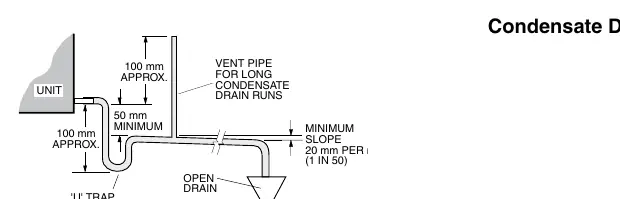
- Trap: The condensate drain must be trapped outside the unit cabinet with a vertical height of at least 50 mm.
- Slope: The drain must have a slope of at least 1 in 50 (20 mm per meter).
- Ventilation: For long condensate pipe runs, install a vent pipe near the trap. The top of the vent pipe must be at least 100 mm above the unit's drain tray.
- Testing: Always check the drainage system by pouring water into the drain tray to ensure it discharges correctly without overflowing.
Electrical Wiring and Connections
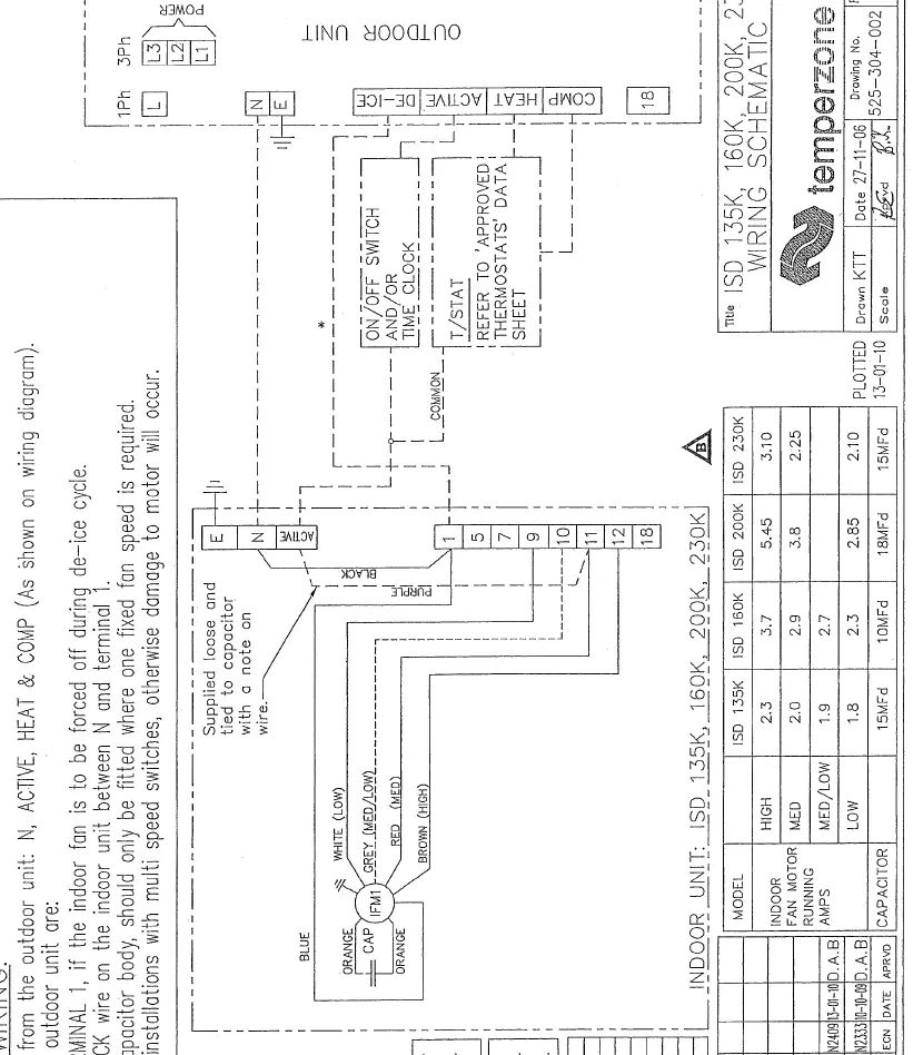
Electrical work must be performed by a qualified electrician in accordance with local regulations and the provided wiring diagram. The electrical supply is specified on the Outdoor Unit's wiring diagram. If 'Indoor Fan Off During De-Ice' is required, a spare wire should be run between the indoor and outdoor units.
Air Filtration and Heating Options
- Filter Box: If installed, the filter box replaces the return air spigot. It increases the spigot depth from 60 mm to 140 mm.
- Electric Heater Box: If installed, it replaces the supply air spigot, increasing the depth from 60 mm to 195 mm.
Commissioning
- Verify the thermostat is correctly wired and set to the desired temperature.
- Ensure the air filter (if fitted) is clean.
- Check that the fan runs freely without vibration.
- Confirm the condensate drain is clear and draining freely.
- Run the unit in both cooling and heating modes to verify operation.
Maintenance Schedule
- Weekly (First Four Weeks): Check air filter and vacuum if necessary; check condensate drain for free drainage.
- Monthly: Check air filter and vacuum if necessary.
- Six Monthly: Check condensate drain, heat exchanger coil (vacuum/brush clean), fan tightness, fan motor operation, electrical connections, and air supply at diffuser outlets.
Noise Isolation
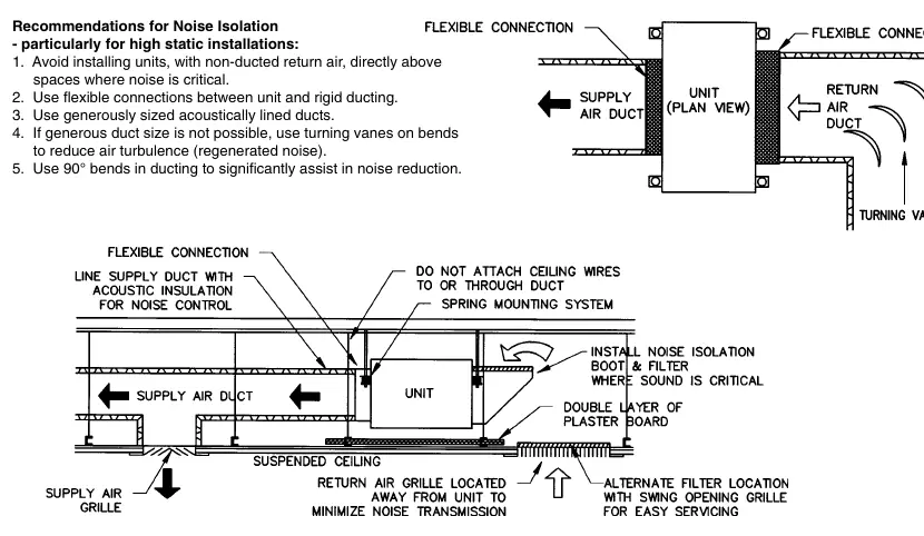
For high static installations where noise is critical, avoid installing units with non-ducted return air directly above sensitive spaces. Use flexible connections between the unit and rigid ducting, utilize acoustically lined ducts, and incorporate 90-degree bends in ducting to reduce regenerated noise.
Practical help
Common problems
Water carry-over
If air returning to the unit is expected to be above 50% RH, limit coil face velocity to 2.5 m/s or less and select a fan speed that avoids water carry-over.
Excessive noise
Use flexible connections, acoustically lined ducts, and 90-degree bends in ducting. Avoid non-ducted return air directly above critical spaces.
Drainage overflow
Ensure the trap is at least 50mm deep, the slope is at least 1 in 50, and the drain is not piped to a level above the unit drain tray.
Before use
- Verify thermostat is correctly wired and set.
- Ensure air filter is clean.
- Check that the fan runs freely without vibration.
- Confirm condensate drain is clear.
- Run the unit in both cooling and heating modes.
Specs in practice
- Condensate Drain Slope
- Minimum 20mm per meter (1 in 50) to ensure proper water flow.
- Condensate Trap Height
- Minimum 50mm vertical height required to prevent air/water issues.
- Electrical Clearance
- Minimum 500mm clearance required to the electrical box for maintenance.
Images and diagrams
- Fig 1: Dimensions and mounting centers for ISD units.
- Fig 2 & 3: Spring vs Solid mounting methods.
- Fig 4: Condensate drain trap and vent pipe configuration.
- Fig 5: Noise isolation recommendations for ducting.
Model compatibility
- Designed for use ONLY with R410A refrigerant.
- Compatible with specific OSA outdoor units (refer to manual for combinations).
- Requires SAT-2 or TZT-701 controller for operation.

Manual page author
Michael Turner
Technical manual editor
Reviews PDF manuals for structure, safety notes, and practical product details so readers can find the right information quickly.