HVAC / Packaged Rooftop Units
Installation and Maintenance Guide for Temperzone IMDL 130Y Ducted Fan Coil Unit
Comprehensive installation and maintenance guide for the Temperzone IMDL 130Y Ducted Fan Coil Unit. Includes mounting instructions, water connection details, electrical wiring diagrams, fan control settings, and maintenance schedules.
Table of contents
Manual images
Click an image to enlargeQuick guide from the manual
The Temperzone IMDL 130Y is a ducted fan coil unit requiring specific installation and maintenance procedures. Key requirements include a minimum of 500 mm clearance at the electrical box end for service access and ensuring the unit is installed level. The system supports either 0-10V DC variable control or 3-step contact input control, but not both simultaneously. Proper condensate drainage with a minimum slope of 1 in 50 is critical for operation.
Installation and Mounting
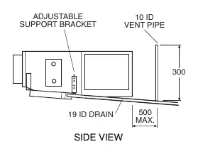
The unit must be installed in accordance with national and local safety codes. It can be suspended using threaded rods or bolts with locking nuts (not supplied) or mounted on vibration isolators on a suitable platform. Ensure the unit is level. Use the adjustable support bracket to lower the drain pipe outlet to maintain the required slope in the drain tray.
Water Supply and Drain
The unit features male pipe threaded IN and OUT water connections. Overtightening these connections may damage the unit. It is recommended to use Temperzone 600 mm flexible high-pressure water hoses. The maximum water pressure for the hoses is 1720 kPa (250 psi), while the unit itself can withstand 4480 kPa (650 psi). The condensate drain must have a slope of at least 1 in 50 and must not be piped to a level above the drain tray. A vent pipe must be fitted within 500 mm of the unit.
Electrical Wiring and Fan Control
Electrical work must be performed by a qualified electrician. The unit requires a 1-phase 230V a.c. 50Hz supply with a dedicated circuit breaker. Fan control is achieved via 0-10V DC signal or contact inputs. For 0-10V control, the fan stops below 1.6V, operates at the selected low level between 1.6V and 2.0V, and reaches the high level at 10V. DIP switches on the Analog Level Controller (ALC) are used to configure low and high fan control voltage levels. If electric heat is fitted, the minimum control voltage is raised to 4V.
Maintenance Schedule
- Weekly (First Four Weeks): Check air filter and vacuum clean if necessary; check condensate drain for free drainage.
- Monthly: Check air filter and vacuum clean if necessary.
- Six Monthly: Check condensate drain; check heat exchanger coil (vacuum or brush clean); check fan tightness and motor operation; check electrical connections; check air supply at diffuser outlets.
Practical help
Common problems
Water carry-over
Select fan control levels that avoid water carry-over problems.
Electric heat not working
Check if the manual high-temperature safety thermostat (120°C) requires resetting.
Drainage issues
Ensure the drain pipe has a slope of at least 1 in 50 and is not piped higher than the drain tray.
Before use
- Verify thermostat is correctly wired and set to the desired temperature.
- Ensure the air filter is clean.
- Check that the fan runs freely without vibration.
- Confirm the condensate drain is clear by pouring water into the tray.
- Ensure the unit is level and mounted securely.
Images and diagrams
- Fig 1: Provides overall dimensions and locations for water connections and electrical box.
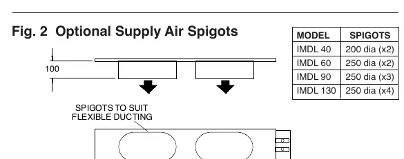
- Fig 2: Shows optional supply air spigot configurations.
- Fig 3: Illustrates the condensate drain setup, including the vent pipe and adjustable support bracket.
Model compatibility
- Compatible with 0-10V DC control or 3 contact inputs (only one method can be connected at a time).
- Requires 1 phase 230V a.c. 50Hz power supply.
- Electric heater elements are factory fitted options.

Manual page author
David Miller
Documentation analyst
Organizes user manual content into clear summaries, with attention to model details, product context, and everyday usability.