HVAC / Packaged Rooftop Units
Temperzone Economiser and Spill Air Outlet Cowls Installation Instructions
Installation guide for Temperzone Economiser, Fresh Air Inlet, and Spill Air Outlet Cowls for OPA 1410–2110 RLT units. Includes assembly steps, component lists, and clearance requirements.
Table of contents
Manual images
Click an image to enlargeQuick guide from the manual
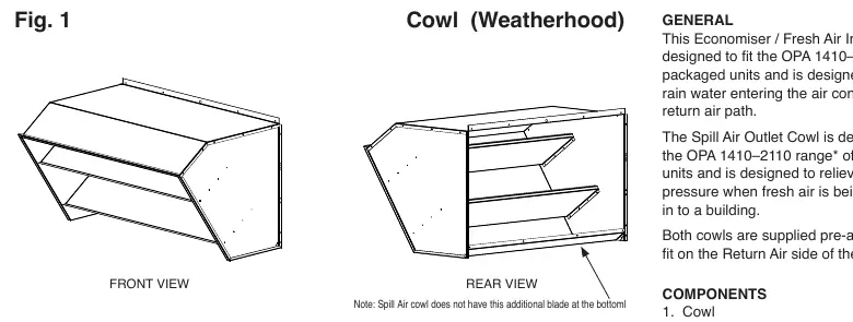
This document provides installation instructions for the Economiser, Fresh Air Inlet, and Spill Air Outlet Cowls designed for the Temperzone OPA 1410–2110 RLT range. These cowls are pre-assembled and intended to prevent rain water from entering the return air path and to relieve excess air pressure. Important: A silicon sealant (not supplied) is required for installation, and a minimum of 300 mm clearance is required beneath the Fresh Air cowl to prevent rain bounce-back.
Components
- Cowl
- M6 x 13 SKT hex head screws (x10)
Assembly
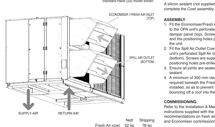
- Fit the Economiser/Fresh Air Inlet Cowl to the OPA unit's perforated Economiser damper panel (top). Use the supplied screws and pre-drilled positioning holes.
- Fit the Spill Air Outlet Cowl to the OPA unit's perforated Spill Air damper panel (bottom). Use the supplied screws and pre-drilled positioning holes.
- Ensure all joints are sealed with silicon sealant.
- Maintain a minimum of 300 mm clearance beneath the Fresh Air cowl after installation.
Commissioning
For recommendations on fresh air damper use and Economiser commissioning, refer to the Installation & Maintenance instructions supplied with the OPA unit.
Practical help
Common problems
Rain water entering the air conditioner's return air path
Install the Economiser/Fresh Air Inlet Cowl as per the instructions.
Excess air pressure in the building
Install the Spill Air Outlet Cowl to relieve pressure when fresh air is introduced.
Before use
- Verify all components (Cowl, 10x M6 screws) are present.
- Check for transit damage.
- Obtain silicon sealant (not supplied).
- Ensure 300 mm clearance space is available beneath the Fresh Air cowl location.
Specs in practice
- Fresh Air cowl weight
- 52 kg (Nett) / 78 kg (Shipping)
- Spill Air cowl weight
- 50 kg (Nett) / 76 kg (Shipping)
Images and diagrams
- Fig. 1 shows the Cowl (Weatherhood) from front and rear views.
- Fig. 2 illustrates the installation position of the Economiser/Fresh Air Inlet (top) and Spill Air Outlet (bottom) on the OPA unit.
Model compatibility
- Designed for OPA 1410–2110 RLT range of packaged units.
- Not applicable to some Supply/Return Air configurations; refer to Temperzone.

Manual page author
Michael Turner
Technical manual editor
Reviews PDF manuals for structure, safety notes, and practical product details so readers can find the right information quickly.