HVAC / Air Conditioners
Installation and Maintenance Manual for Temperzone OPA 116RKTY Air Conditioner
Comprehensive installation and maintenance guide for the Temperzone OPA 116RKTY air conditioner. Includes detailed instructions on positioning, condensate drainage, electrical wiring, fan speed adjustments, start-up procedures, and routine...
Table of contents
Manual images
Click an image to enlargeQuick Guide from the Manual
This document provides essential installation, operation, and maintenance instructions for the Temperzone OPA 116RKTY air conditioner. Before starting, ensure the unit is installed by a qualified professional in accordance with local safety codes. A critical requirement is a 24-hour power supply to the crankcase heaters prior to start-up to protect the compressor.
Installation
Positioning: Refer to the dimension diagram for minimum clearances. If placing multiple units side-by-side, allow at least 2 meters between coil faces.
Mounting: Fasten the unit to a firm, flat, horizontal base using the four holes in the mounting rails. If installing on a roof, use a substantial structure with anti-vibration mounts or pads.
Condensate Drain: The drain must be 'U' trapped outside the unit with a vertical height of at least 50 mm. The drain line should have a slope of at least 1 in 50.
Electrical Requirements
Electrical work must be performed by a qualified electrician. The unit must be wired directly from a distribution board via a circuit breaker and mains isolator. A 24-hour power supply to the crankcase heaters is mandatory to maintain warranty coverage.
Indoor Fan Speed Adjustment
The indoor fan speed can be adjusted via the UC7 Controller board:
- Ensure the compressor is off and not requested to start.
- Press and hold the SW3 push button on the UC7 board until the display shows 'H' (for High speed), then release.
- The display will show the current voltage (factory default 7.5V).
- Press SW3 to increase voltage in 0.5V steps (up to 10.0V).
- Wait 30 seconds for the controller to save the setting.
- To adjust 'Low' speed, repeat the process but wait until the display shows 'L' before releasing the button (factory default 5.5V).
Start-up Procedure
- Switch on the unit after the 4-hour crankcase heater delay.
- Check for correct compressor rotation. If incorrect, the compressor will be noisy and draw minimal current; correct by changing phasing at the main power terminal.
- Check supply voltage.
- Measure current draw on the compressor and fan motors against specified values.
Maintenance Schedule
Weekly (First Four Weeks)
- Check indoor air filters; vacuum or wash if necessary.
- Check condensate drain for free drainage.
- Inspect compressor compartment for oil stains (indicates refrigerant leaks).
- Check tightness of electrical connections.
Six Monthly
- Check tightness of fan and motor mountings.
- Check electrical connections.
- Check suction and discharge operating pressures.
- Replace indoor air filters.
- Check condensate drain.
Yearly
- Check refrigerant piping for chafing and vibration.
- Check operation of electric heaters (if fitted).
- Check air supply at all diffusers.
- Check for excessive noise/vibration.
- Check insulation and duct damage.
- Clean lint and dust from outdoor coil fins.
- Touch up paintwork to prevent corrosion.
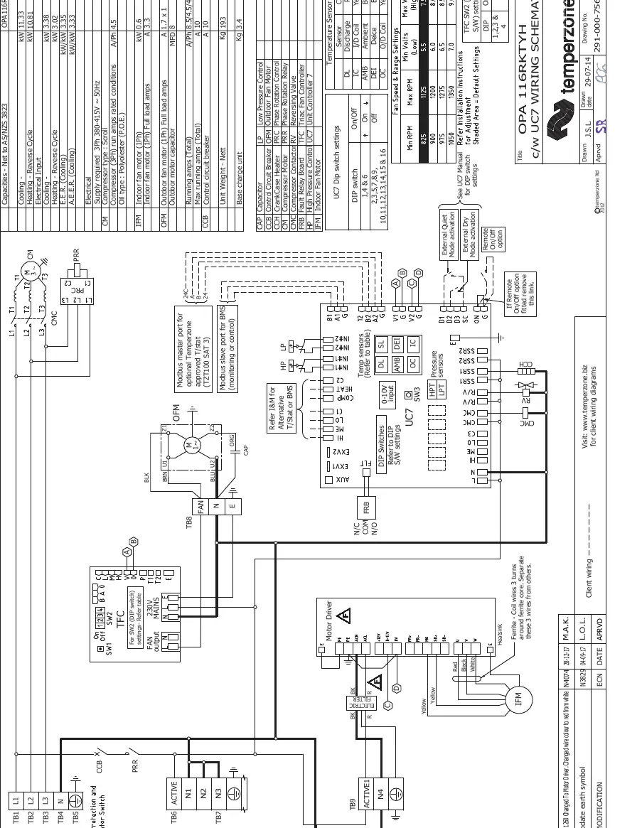
Unit Controller (UC7)
The UC7 controller provides system protection, including coil frost protection, de-icing, high head pressure, and low suction pressure cut-out. It also manages compressor cycling and head pressure control. For fault diagnostics, refer to the UC7 label on the unit or visit www.temperzone.biz.
Official resources from the manual
Practical help
Common problems
Compressor is noisy and not pumping
Check for correct rotation. If incorrect, change the phasing at the main power terminal.
Water carry-over issues
If humidity is expected to be above 50%RH, limit coil face velocity to 2.5 m/s or less and select a fan speed that avoids carry-over.
Compressor won't start
Ensure the 4-hour crankcase heater delay period has expired.
Before use
- Ensure 4-hour crankcase heater delay has passed.
- Check that all fan motors are free running.
- Verify thermostat is correctly wired and set to the desired temperature.
- Ensure air filters are correctly installed.
- Check that all supply air diffuser dampers are open.
Images and diagrams
- Fig 1: Provides dimensions, mounting centers, and point loads for the OPA 116RKTY unit.
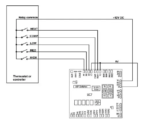
- Fig 2: Wiring diagram for connecting alternative thermostats using 12V DC control signals.
Model compatibility
- Requires 3Ph 380-415V ~ 50Hz power supply.
- Compatible with thermostats with manual Heat/Cool selection or automatic changeover.

Manual page author
David Miller
Documentation analyst
Organizes user manual content into clear summaries, with attention to model details, product context, and everyday usability.