HVAC / Heat Pumps
User Manual for Temperzone VPA 160RKTG-DP Air Cooled Packaged Unit
Quick guide for the Temperzone VPA 160RKTG-DP air cooled packaged unit. Includes installation, wiring, commissioning, maintenance, and troubleshooting procedures.
Table of contents
Manual images
Click an image to enlargeQuick guide from the manual
The Temperzone VPA 160RKTG-DP is an air cooled packaged unit featuring a digital scroll compressor and UC8 controller. Important: Before starting the compressor, a 4-hour crankcase heater delay is required. Ensure mains power is switched on during this period. The unit must be installed by a qualified professional in accordance with local regulations.
Installation
The unit should be fastened to a firm, flat horizontal base using the mounting channels. If installing on a roof, use a substantial structure with vibration-isolating mounts. Flexible duct connections are recommended.
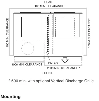
- Clearances: Maintain at least 1000mm at the front, 100mm at the sides and rear. If units are side-by-side, allow at least 2m between coil faces.
- Condensate Drain: The drain is U-trapped inside the unit. Direct the outlet to a suitable disposal site.
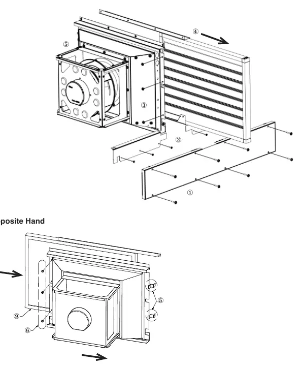
- Vertical Discharge Grille: If using the optional grille, secure it using the supplied screws and pre-drilled holes.
Wiring and Controls
Electrical work must be performed by a qualified electrician. The unit requires a direct connection from a distribution board via a circuit breaker and mains isolator.
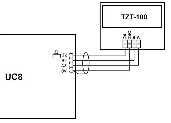
- Control Options: The unit supports TZT-100 wall thermostats, 24V AC/0-10V external signals, remote on/off switches, Modbus RTU, and BACnet-IP (with optional gateway).
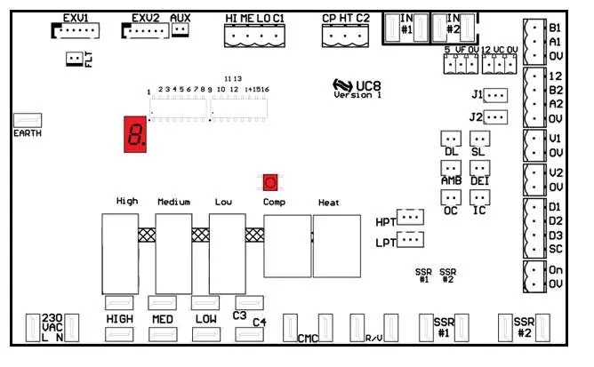
- Capacity Control: Managed via the UC8 controller. DIP switch 14 selects between Standard (OFF) and Close (ON) capacity control modes.
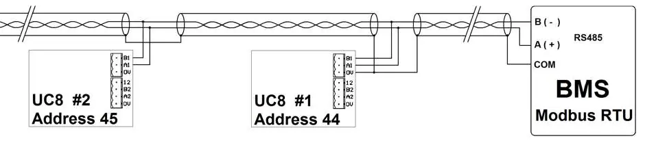
- Modbus RTU: For monitoring and control, daisy-chain connections using shielded twisted pair cable. Ensure each UC8 controller has a unique device address.
Start-Up Procedure
Before commissioning, ensure the 4-hour crankcase heater delay has passed. To commission:
- Place the UC8 Controller in commissioning mode by holding the push button until the display shows 'c'.
- Start the compressor in cooling mode and check for correct rotation.
- Measure current draw on each phase and verify against specifications.
- Test heating mode operation.
- Adjust indoor fan speed if necessary using the UC8 display and push button.
Operation
The UC8 controller manages safety timers and protection functions. If the compressor is held off or on by a safety timer, the display shows 'H-O-L-d'. The unit features a single variable capacity digital scroll compressor.
Maintenance
Monthly: Check air filter (vacuum or wash), check condensate drain, inspect compressor compartment for oil stains, and check system operating pressures via UC8.
Six Monthly: Check tightness of electrical connections, inspect for corrosion in high salt atmospheres, check fan/motor mountings, and check/replace indoor air filter.
Yearly: Check refrigerant piping for chafing/vibration, test electric heaters, check air supply at diffusers, inspect for excessive noise, and clean outdoor coil fins with a soft brush or low-pressure water spray.
Troubleshooting
If the unit displays an error code, refer to the UC8 Controller label or the Temperzone website. Common issues include water leaks (check drain trap/slope), heating performance (check for de-icing cycles), and unit lock-out (reset via power cycle or Modbus command).
Practical help
Common problems
Unit is leaking water
Check the drain trap, vent, and slope. If water carry-over occurs, reduce the maximum fan speed.
Heating not working as expected
The unit may be in a de-icing cycle, which reverses the cycle for a few minutes. Check if the unit is correctly sized for the building.
Unit is locked out
Remove mains power for at least 3 seconds, issue an 'unlock' command via Modbus, or reset the controller via Modbus.
Before use
- Ensure mains power is isolated before performing maintenance.
- Verify the compressor is securely mounted.
- Check that the thermostat and controls are correctly wired.
- Ensure air filters are installed.
- Check that air diffusers are open.
- Allow a 4-hour crankcase heater delay before starting the compressor.
Specs in practice
- UC8 Controller
- The main unit controller responsible for system protection, capacity control, and diagnostics.
- Digital Scroll Compressor
- A variable capacity compressor that provides flexibility and energy efficiency.
- 0-10V Signal
- An analog control signal used for capacity management by external controllers.
Images and diagrams
- Wiring diagrams illustrate connections for TZT-100 thermostats, BMS/external controllers, and Modbus RTU daisy-chaining.
- Air handling performance charts display the relationship between airflow, external pressure, and power input.
Model compatibility
- Compatible with TZT-100 wall thermostat.
- Supports Modbus RTU and BACnet-IP serial communications (with optional gateway module).

Manual page author
David Miller
Documentation analyst
Organizes user manual content into clear summaries, with attention to model details, product context, and everyday usability.