Automotive / Lighting Accessories
Tesla Model S Spare 12V Power Circuit Installation Guide
A technical guide for locating and accessing the spare 12V power circuit in Tesla Model S vehicles. Includes procedures for removing interior panels, identifying wiring, and locating fuses for third-party equipment installation.
Table of contents
Manual images
Click an image to enlargeImportant Information
This document provides instructions for locating the spare 12V power circuit in Tesla Model S vehicles built after July 11, 2014. This circuit is intended to provide a switched power source for third-party equipment. Caution: Tapping into the 12V system is done at the user's risk and may result in increased battery drain, potential damage to the 12V battery, reduced driving range, or increased electromagnetic interference (EMI). Tesla does not endorse the use of third-party equipment and does not accept responsibility for damage caused by such installations.
Accessing the Circuit (Vehicles Built Before April 11, 2016)
- Open the front right-hand (RH) door.
- Remove the floor mat if equipped.
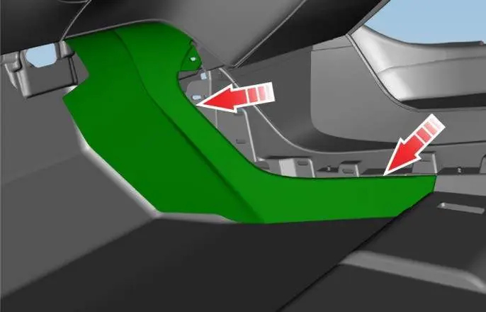
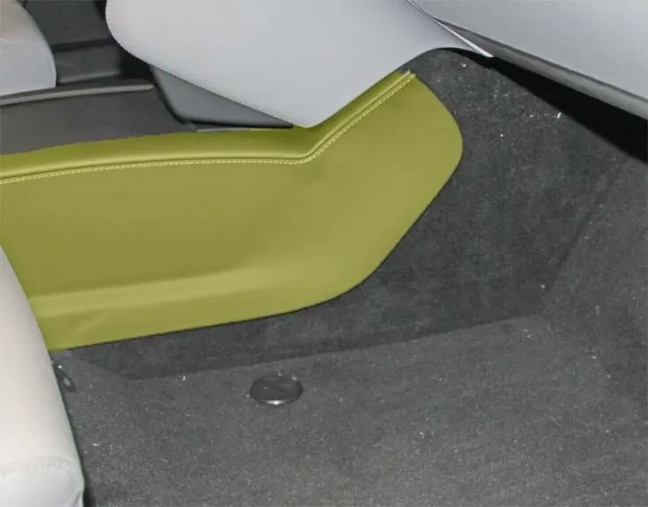
- Release the clips securing the RH wrapped panel.
- Release the clips and adhesive pad securing the RH closeout extension to access the circuit.
Accessing the Circuit (Vehicles Built After April 11, 2016)
- Open the front RH door.
- Remove the floor mat if equipped.
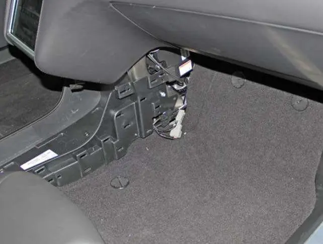
- Gently pull outward on the front of the center console trim panel to release the clips. It is not necessary to fully remove the panel.
- Remove the carpeted closeout panel.
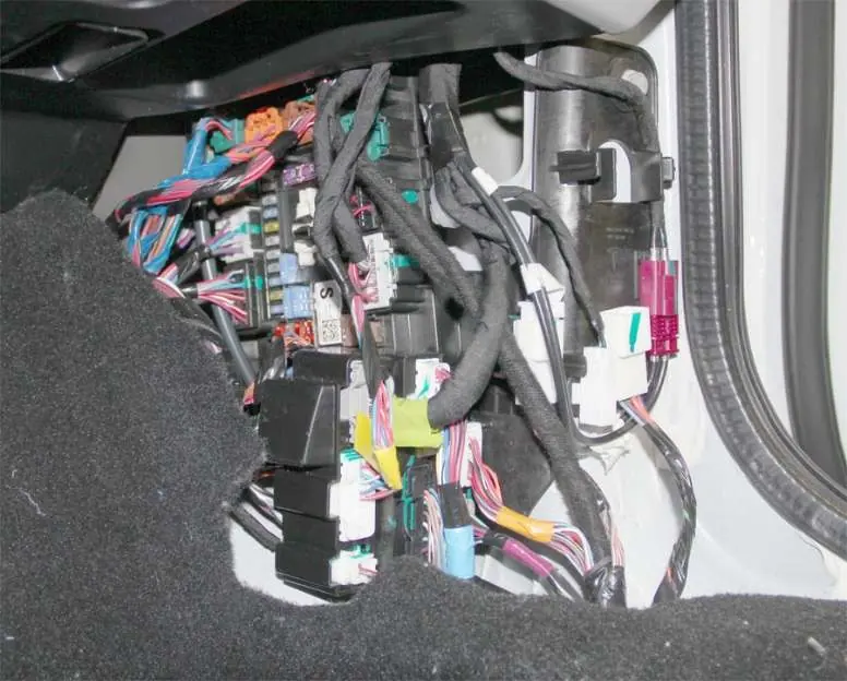
- Use pliers or a similar tool to push in the clip securing the harness connector to the plastic bracket. Once released, gently pull the harness connector out.
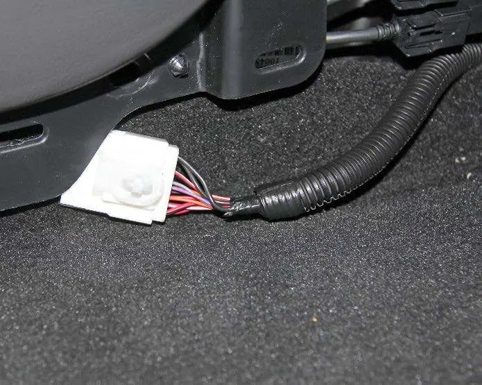
Wiring Identification
The spare 12V positive circuit is identified by a red wire with a white stripe on the gray 4-pin connector (which contains 3 wires). Use either of the black wires on the same connector for chassis ground. Ensure you only use the wires shown in the documentation, as the connector contains other wires with similar colors.
Fuse Locations
The spare 12V power circuit is protected by a fuse:
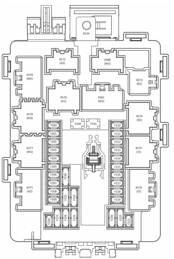
- Vehicles built between July 2014 and September 2015 (LHD) or May 2015 (RHD): Protected by fuse F33 in fuse box 2, located under the maintenance panel in the front trunk.
- Vehicles built between September 2015 and April 2016: Protected by fuse F202 in the front cabin fuse box, located at the base of the RH A-pillar.
Technical Specifications
- Continuous Load: Up to 11 A (150 W).
- Peak Load: Up to 15 A (180 W).
- System: Negatively grounded 12V system.
- Circuit Type: Tied to the accessory (ACC) rail.
Practical help
Common problems
Risk of battery damage or EMI
Tapping into the 12V system is at the user's risk; ensure third-party equipment is compatible and properly installed to avoid battery drain or interference.
Identifying correct wires
The connector contains multiple wires with similar colors. Use only the red wire with a white stripe for 12V positive and the black wire for chassis ground.
Before use
- Verify the vehicle's build date to determine the correct access procedure and fuse location.
- Ensure you have pliers or a similar tool to release harness clips.
- Confirm the third-party equipment does not exceed the 11A continuous load limit.
- Ensure the vehicle is powered down or in a safe state before working on electrical components.
Specs in practice
- Continuous Load
- Maximum sustained power draw allowed is 11 A (150 W).
Images and diagrams
- Figures 1-2: Removal steps for RH closeout extension on older models.
- Figure 3: Identification of the 4-pin connector and wiring.
- Figure 4: Location of fuse F33 in the front trunk fuse box.
- Figure 5: Location of fuse F202 in the cabin fuse box.
- Figures 6-7: Removal steps for RH closeout extension on newer models.
Model compatibility
- The spare 12V circuit is tied to the accessory (ACC) rail.
- Tesla does not endorse or support the installation of third-party equipment.

Manual page author
Michael Turner
Technical manual editor
Reviews PDF manuals for structure, safety notes, and practical product details so readers can find the right information quickly.