General / Other Manuals
Thermalright Peerless Assassin 120 Installation Guide
Quick installation guide for the Thermalright Peerless Assassin 120 CPU cooler, covering mounting procedures for Intel LGA 115X/1200/1700/20XX and AMD AM4 sockets, fan connection, and thermal paste application.
Table of contents
Important information from the manual
This guide provides the necessary steps to install the Thermalright Peerless Assassin 120 CPU cooler. It covers hardware compatibility for various Intel and AMD sockets, the correct application of thermal paste, and the proper connection of cooling fans to the motherboard.
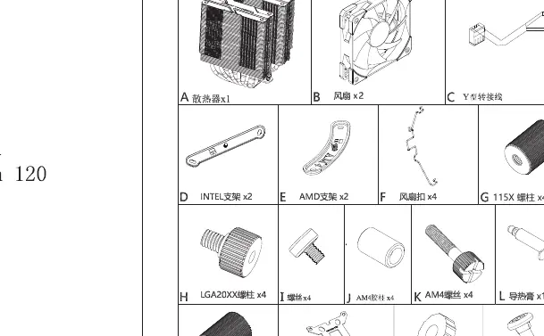
Parts list
- A: Heatsink
- B: Fan
- C: Y-splitter cable
- D: Intel bracket
- E: AMD bracket
- F: Fan clip
- G: 115X screw bolt
- H: LGA20XX screw
- I: Tightening nut
- J: AM4 screw
- K: AM4 standoff
- L: Thermal grease
- M: 1700 screw bolt
- N: LGA115X/1700 backplate
- O: Plastic pad
- P: Screw
Installation
AMD AM4: Remove the original plastic support, keep the backplate, and lock it to the motherboard with the AM4 rubber column. Apply thermal paste, secure the main body with a screwdriver, and attach the fan with a fan wire.
Intel LGA 115X/1200: Install the Intel backplate from the back of the motherboard, place plastic standoffs from the front, and install the Intel metal brackets with screws. Apply thermal paste, secure the main body, and attach the fan.
Intel LGA 20XX: Thread the LGA 20XX screw bolts onto the brackets and tighten with nuts. Apply thermal paste, secure the main body, and attach the fan.
Intel LGA 1700: Install the Intel backplate from the back of the motherboard, place plastic standoffs from the front, and install the Intel metal brackets with screws. Apply thermal paste, secure the main body, and attach the fan.
Fan connection
Insert the 4-pin PWM fan header into the CPU_FAN socket on the motherboard. Use the included Y-splitter cable to sync fan speed for dual fan setups. For ARGB lighting, connect the 3-pin (5V) ARGB header to the motherboard ARGB lighting socket or lighting controller.
Practical help
Common problems
Fan speed synchronization
Use the included Y-splitter cable to connect both fans to the CPU_FAN header on the motherboard.
ARGB lighting not working
Ensure the 3-pin (5V) ARGB header is connected to a compatible motherboard ARGB socket or an external lighting controller.
Before use
- Verify all parts from the parts list are present.
- Identify your specific CPU socket type (Intel LGA 115X/1200/1700/20XX or AMD AM4).
- Ensure you have a screwdriver available for mounting.
- Clean the CPU surface before applying thermal grease.
Specs in practice
- 3-pin (5V) ARGB
- Connector for addressable RGB lighting; do not connect to 12V headers.
Images and diagrams
- The manual uses specific screw sets for different Intel sockets (LGA 115X/1700 vs 20XX).
- AMD installation requires retaining the original motherboard backplate.
Model compatibility
- Supports Intel LGA 115X, 1200, 1700, 20XX.
- Supports AMD AM4.

Manual page author
David Miller
Documentation analyst
Organizes user manual content into clear summaries, with attention to model details, product context, and everyday usability.