General / Other Manuals
Thermaltake The Tower 300 Micro Tower User Manual
Quick guide for the Thermaltake The Tower 300 Micro Tower, covering installation steps for components, cooling systems, and technical specifications.
Table of contents
Manual images
Jump to the sectionQuick guide from the manual
This document provides essential installation and configuration instructions for the Thermaltake The Tower 300 Micro Tower. It covers component compatibility, hardware installation, and cooling system setup.
Product Introduction
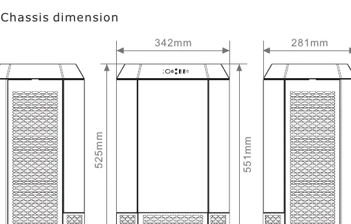
The Tower 300 is a Micro Tower chassis supporting Mini ITX and Micro ATX motherboards. It features tempered glass side panels and extensive cooling support.
Installation Guide
Power Supply Unit (PSU) Installation
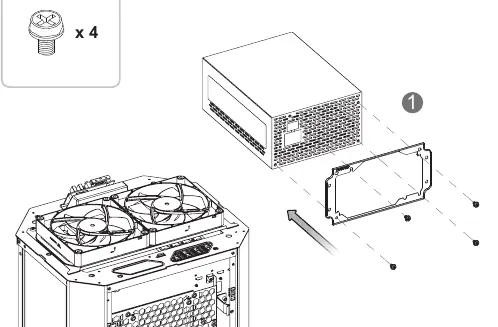
- Remove the necessary panels to access the PSU mounting area.
- Slide the PSU into the designated slot and secure it using the provided screws.
Motherboard Installation
- Prepare the motherboard standoffs.
- Align the motherboard with the standoffs and secure it using the appropriate screws.
HDD Installation
The case supports both 3.5" and 2.5" drives. Mount the drives onto the designated brackets and secure them with the provided screws before attaching the brackets to the chassis.
VGA Card Installation
- Remove the expansion slot covers.
- Insert the VGA card into the PCIe slot and secure it to the chassis.
Air and Liquid Cooling Installation
The chassis supports various fan and radiator configurations:
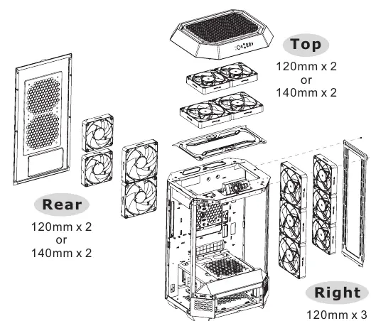
- Top: 2 x 120mm or 2 x 140mm fans.
- Right Side: Up to 3 x 120mm/140mm fans or a 360mm/420mm AIO radiator.
- Rear: 2 x 120mm or 2 x 140mm fans.
- Power Cover: 1 x 120mm or 140mm fan.
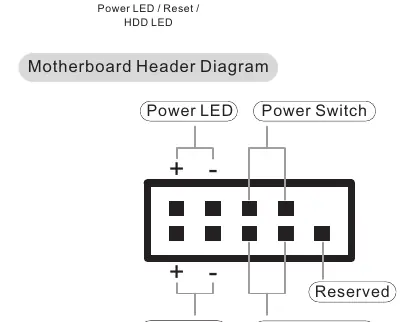
I/O Connection
Connect the front panel cables (Power SW, Reset, HDD LED, Power LED) to the corresponding headers on your motherboard. Connect the USB 3.0 and Type-C cables to the internal motherboard headers.
Maintenance
To maintain optimal airflow, regularly remove and clean the dust filters located on the exterior panels of the chassis.
Manufacturer information
Thermaltake
Practical help
Common problems
VGA card does not fit
Ensure the card length is within 280mm if using the power cover, or 400mm if the power cover is removed.
CPU cooler too tall
The maximum supported CPU cooler height is 210mm.
Before use
- Verify motherboard compatibility (Mini ITX or Micro ATX).
- Check PSU length (max 220mm).
- Ensure all necessary screws are available (refer to the accessory list).
- Plan your cooling configuration (Air vs AIO).
Specs in practice
- Motherboard Support
- 6.7" x 6.7" (Mini ITX), 9.6" x 9.6" (Micro ATX)
- VGA Length Limitation
- 280mm with power cover, 400mm without
- CPU Cooler Height Limitation
- 210mm
Images and diagrams
- The manual provides exploded views for removing panels to access the interior.
- The I/O connection diagram shows the pinout for the motherboard headers.
- The cooling diagrams illustrate fan and radiator placement options for each side of the case.
Model compatibility
- Supports standard PS2 PSUs.
- Supports up to 420mm AIO radiators on the right side.

Manual page author
Michael Turner
Technical manual editor
Reviews PDF manuals for structure, safety notes, and practical product details so readers can find the right information quickly.