Tools / Air Tools Painting
Operation Manual for Titan PowrCoat Series Air Powered Airless Sprayer
Comprehensive operation manual for the Titan PowrCoat series air-powered airless sprayers. Includes detailed instructions for setup, operation, pressure relief, cleaning, maintenance, and troubleshooting.
Table of contents
Manual images
Click an image to enlargeQuick Guide from the Manual
The Titan PowrCoat series are air-powered airless sprayers designed for high-pressure coating applications. Before starting, ensure the unit is properly grounded, all connections are secure, and the air compressor meets the required specifications. Always follow the Pressure Relief Procedure before performing any maintenance, cleaning, or when leaving the unit unattended.
Safety Regulations
Warning: Danger of injection injury. High-pressure streams can pierce the skin and cause serious injury. Never point the spray gun at yourself or others. Always use the trigger lock when not spraying. Ensure the unit is properly grounded to prevent static discharge, which can cause fires or explosions, especially when using flammable solvents.
Setup and Installation
- Connect the siphon hose to the fluid section and the bleed hose to the bleed valve.
- Attach a minimum of 50' (15m) of 3/8" nylon airless spray hose to the material outlet.
- Fill the oil cup 1/2 full with Piston Lube to extend packing life.
- Ensure the air compressor is located outside the immediate spraying area.
- Connect the air hose to the air inlet and tighten securely.
Operation
To prepare a new sprayer, flush the system with a compatible cleaning agent to remove test fluids. When preparing to spray, ensure the fluid is compatible with the paint. Adjust the air regulator to achieve the desired spray pattern, ensuring the gauge does not exceed 100 PSI (6.9 bar). Always test the spray pattern on a piece of cardboard before applying to the surface.
Pressure Relief Procedure
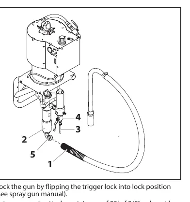
- Lock the spray gun trigger.
- Close the shutoff valve.
- Slowly open the bleed valve by turning it counterclockwise.
- Unlock the gun and hold the metal part firmly against a metal waste container to discharge static electricity.
- Trigger the gun to release remaining pressure.
- Lock the gun trigger.
Cleanup and Maintenance
Clean the sprayer thoroughly after daily use to prevent material buildup. Use compatible solvents for cleaning. Check the air filter after every use. Perform daily maintenance by lubricating the upper packings with Piston Lube and cleaning the inlet screen. The air motor requires inspection every 1500 hours of service.
Troubleshooting
If the unit experiences issues such as spitting, failure to shut off, or poor spray patterns, refer to the troubleshooting section for specific causes and solutions. Common fixes include cleaning the gun, replacing worn tips, adjusting material pressure, or checking for air leaks in the suction system.
Practical help
Common problems
Spitting gun
Inspect connections for air leaks, disassemble and clean the gun, or adjust/replace the needle assembly.
Gun will not shut off
Replace or adjust the needle and seat, or clean the gun.
Insufficient material supply
Increase material pressure at the pump, clean or replace the gun/pump filters, or check for a blocked tip.
Motor stops at top or bottom of stroke
Tighten the piston rod connection, check for broken trip springs, or check the AirCare fluid level in the automatic lubricator.
Before use
- Ensure the unit is properly grounded/earthed.
- Check all hose connections for leaks.
- Verify the air compressor meets the power requirements.
- Fill the oil cup 1/2 full with Piston Lube.
- Ensure the spray gun trigger lock is engaged.
- Check the air filter for debris.
Specs in practice
- Pressure Ratio
- The ratio of air pressure input to fluid pressure output (e.g., 45:1 means 100 PSI air input results in 4500 PSI fluid output).
- Max. operating pressure
- The maximum pressure the unit can safely handle (varies by model: 4500-7200 PSI).
- Max. air inlet pressure
- The maximum air pressure allowed from the compressor (100 PSI / 6.9 bar).
Images and diagrams
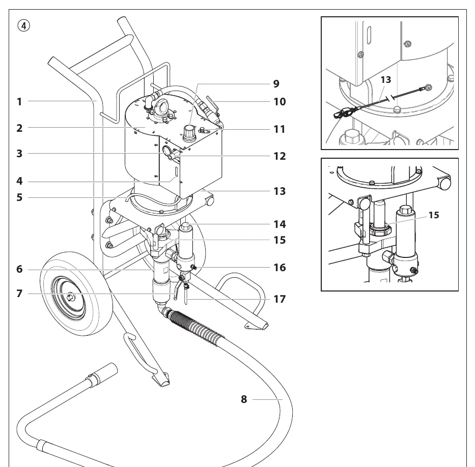
- System diagram (Page 8) identifies key components like the air motor, air regulator, and fluid pump.
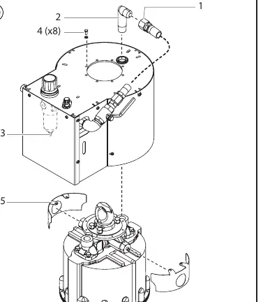
- Filter assembly diagram (Page 16) shows the filter element, support, and PTFE gaskets.
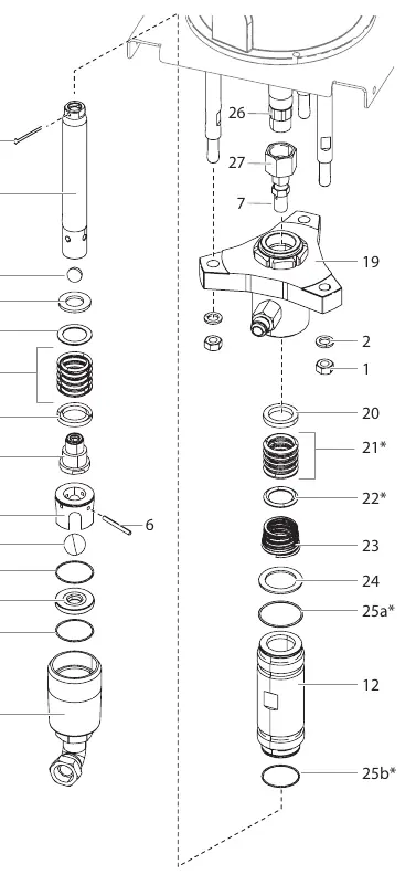
- Fluid pump assembly diagram (Page 22) details the packing sets and valve components.
Model compatibility
- Use only manufacturer authorized parts.
- Do not use paint or solvent containing halogenated hydrocarbons (e.g., chlorine, bleach, trichloroethane) as they are incompatible with aluminum.

Manual page author
Michael Turner
Technical manual editor
Reviews PDF manuals for structure, safety notes, and practical product details so readers can find the right information quickly.