Garden / Garden Tools
Toro 13-32H Rear-Engine Riding Mower Parts Catalog
Official parts catalog for the Toro 13-32H rear-engine riding mower (Model 70186). This guide provides exploded diagrams and part lists for all major assemblies, including the deck, steering, transmission, and Briggs & Stratton engine...
Table of contents
Manual images
Click an image to enlargeHow to use this parts catalog
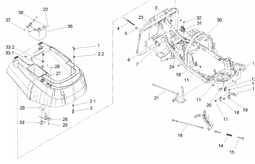
This catalog is designed to help you identify and order replacement parts for the Toro 13-32H Rear-Engine Riding Mower (Model 70186). Each section contains an exploded view diagram of a specific assembly, followed by a table listing the reference numbers, part numbers, quantities, and descriptions of the components.
Ordering replacement parts
To ensure you receive the correct components, please provide the following information to your local dealer:
- The specific part number.
- The quantity required.
- A brief description of the part.
Understanding reference numbers
The catalog uses specific formats to identify parts in the illustrations:
- Standard Reference: A simple number corresponding to the part list.
- Service Assembly Reference (a:b): The 'a' represents the assembly reference number, and 'b' represents the unique part number within that assembly. Ordering the assembly reference number (a) will provide all parts listed under that assembly.
- Quantity Reference (nX y): The 'n' is the quantity, 'X' is the multiplication symbol, and 'y' is the reference number. For example, 2X 37 indicates two of the parts identified by reference number 37.
Assemblies covered
This catalog includes detailed diagrams and parts lists for the following systems:
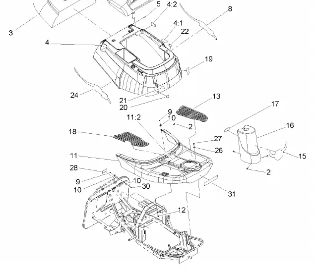
- Body and Decal Assembly: Covers the chassis, covers, and decals.
- Seat and Rear Bag Assembly: Includes the seat, bag frame, and mounting hardware.
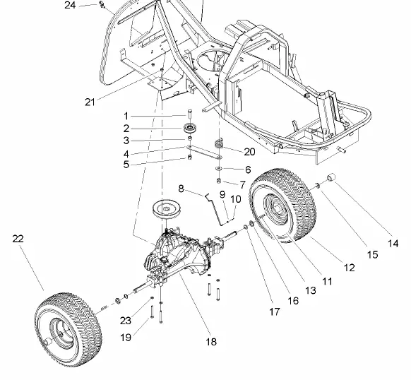
- Front Axle and Steering Assembly: Details the steering rack, tie rods, and front wheel components.
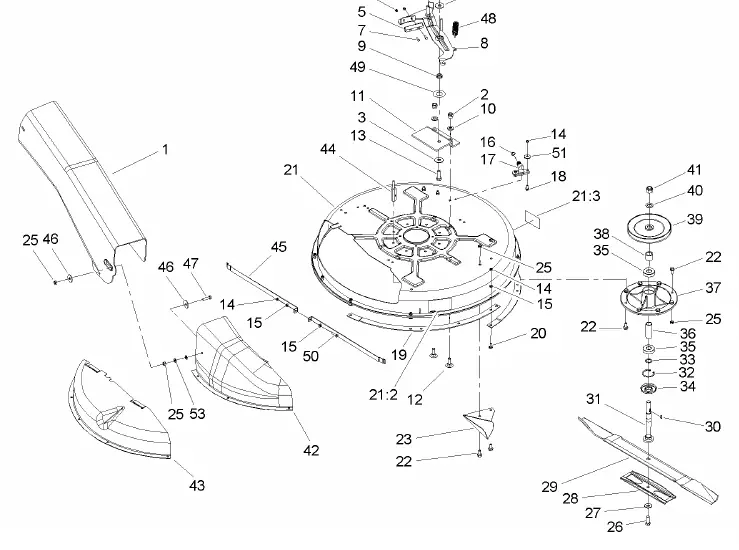
- Deck and Spindle Assembly: Covers the mower deck, blades, pulleys, and spindle components.
- Deck Suspension Assembly: Details the lift levers, brackets, and springs.
- Rear Wheel and Transmission Assembly: Includes the hydro transaxle, rear wheels, and drive components.
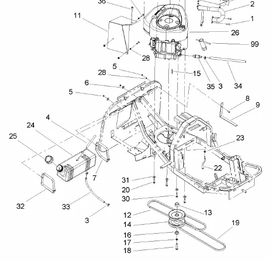
- Engine and Fuel Tank Assembly: Covers the fuel system, exhaust, and engine mounting.
- Electrical and Cable Assembly: Details the ignition, battery, wiring harness, and control cables.
- Briggs & Stratton Engine Components: Includes specific diagrams for the Cylinder, Cylinder Head, Crankshaft, Oil Filter/Pump, Crankcase, Carburetor, Governor, Blower Housing, and Starter assemblies.
Part description abbreviations
The parts lists use standard abbreviations for descriptions, such as:
- ASM: Assembly
- HH: Hex Head
- HHF: Hex Head Flange
- TAP: Self Tapping
- LH/RH: Left Hand / Right Hand
- PTO: Power Take Off
Practical help
Common problems
Identifying the correct part number
Locate the part in the exploded diagram for the relevant assembly, find its reference number, and match it to the corresponding part list table.
Ordering parts for a service assembly
If a part is listed as part of a service assembly (e.g., 6:1), you can order the entire assembly (6) or the individual part (6:1) depending on your needs.
Before use
- Verify your mower's model number is 70186.
- Identify the specific assembly (e.g., Deck, Steering) where the part is located.
- Locate the reference number in the exploded diagram.
- Check the corresponding parts list for the correct part number and quantity.
- Confirm if the part is part of a larger assembly or a standalone item.
Specs in practice
- a:b Reference Format
- Assembly reference number (a) followed by the unique part number within that assembly (b).
Images and diagrams
- Exploded views show the assembly order of components.
- Reference numbers in diagrams correspond directly to the adjacent parts lists.
Model compatibility
- Parts are specific to Toro Model 70186.
- Engine parts are specific to Briggs & Stratton engine 31G777-0121-E1.

Manual page author
Emily Carter
User documentation editor
Prepares concise manual descriptions and highlights the most useful setup, operation, and maintenance information for readers.