Garden / Outdoor
12V Potable Water Pump VEVOR NMDP52 Series
Quick guide for the VEVOR 12V Potable Water Pump (NMDP52-G50-70-12 / NMDP52-G55-70-12). Includes installation steps, troubleshooting, and pressure adjustment instructions.
Table of contents
Manual images
Click an image to enlargeQuick Guide
The VEVOR 52 Series is a heavy-duty, 5-chamber diaphragm pump designed for pressurized water systems in yachts, RVs, caravans, and other applications. It features a built-in bypass function to reduce rapid cycling and is capable of self-priming and running dry.
Specifications
- Rated Voltage: 12V
- Rated Pressure: 70 PSI
- Max Flow: 5.0 GPM (NMDP52-G50-70-12) or 5.5 GPM (NMDP52-G55-70-12)
- Inlet/Outlet Diameter: 1/2" MNPT
Installation
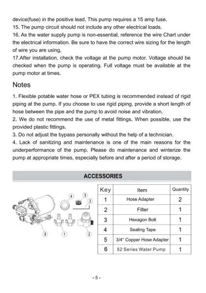
Materials Required: Diaphragm pump, flexible reinforced hose (min 1/2" ID), stainless steel hose clamps, screws, electrical cut-off switch, fuse, screwdriver, and sealant/Teflon tape.


- Mounting: The pump can be mounted in any position. If mounted vertically, the pump head must be in the down position to prevent leakage into the motor casing. Secure the feet without over-compressing them to maintain vibration dampening.
- Plumbing: Use 1/2" ID reinforced hoses. Avoid kinks or restrictive fittings. Install a strainer on the inlet side. If using a check valve, ensure it has a cracking pressure of no more than 2 psi.
- Electrical: Connect to a dedicated circuit. Connect the red (positive) lead to the battery positive terminal and the black (negative) wire to the negative terminal. Install an accessible switch to control power. The circuit must be protected by a 15-amp fuse.
Adjusting the Bypass Valve and Pressure Switch
Caution: Bypass adjustment should be performed by a professional technician using proper gauges. Improper adjustment can damage the pump.
- Remove the pressure switch cover.
- Use a 2mm wrench to adjust the pressure adjustment screw (No. 2). Turn clockwise to increase pressure, counterclockwise to decrease.
- Adjust the bypass valve screws (No. 3) accordingly. Turn clockwise to increase pressure, counterclockwise to decrease.
- The pressure setting for full bypass must be at least 8 psi higher than the shut-off pressure of the pump.
Troubleshooting
- Pulsating Flow: Check lines for kinks, ensure plumbing is not too small, clean filters, and check for air leaks.
- Failure to Prime: Check for air leaks in the intake, debris in valves, punctured diaphragm, or insufficient voltage.
- Motor Won't Start: Check for loose wiring, blown fuse, failed pressure switch, or defective motor.
- Pump Won't Turn Off: Check for leaks in the discharge line, punctured diaphragm, or defective pressure switch.
Maintenance
Regular maintenance and winterization are essential, especially before and after storage. Do not adjust the bypass valve personally without professional assistance.
Manufacturer information
VEVOR
Practical help
Common problems
Pulsating flow (pump cycles on and off)
Check lines for kinks, ensure plumbing fittings are not too small, clean faucets and filters, and check for air leaks.
Motor runs but no pump discharge
Check for restrictions in intake/discharge lines, air leaks in intake, debris in valves, or a punctured diaphragm.
Motor fails to turn on
Check for loose wiring, blown fuse, failed pressure switch, or lack of power to the circuit.
Pump won't turn off
Check for leaks in the discharge line, punctured diaphragm, or defective pressure switch.
Before use
- Ensure 12V power supply is available.
- Use 1/2 inch ID reinforced hoses.
- Install a strainer on the inlet side.
- Use a dedicated electrical circuit with a 15A fuse.
- Check all fittings for air leaks.
- Ensure mounting surface is not too rigid to avoid noise transmission.
Specs in practice
- Rated Pressure
- 70 PSI - The maximum pressure at which the pump is designed to operate.
- Inlet/Outlet Diameter
- 1/2 inch MNPT - The standard thread size for connecting hoses.
Images and diagrams
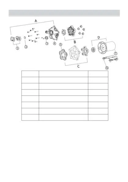
- Exploded view shows the assembly of the pressure switch, bypass valve, pump head, diaphragm, and motor.
- Adjustment diagram illustrates the location of the pressure switch cover and the adjustment screws for the switch and bypass valve.
Model compatibility
- Requires 12V DC power source.
- Use flexible, reinforced hoses; rigid piping is not recommended at the pump connection.
- Not for use with inlet pressure exceeding 30 PSI.

Manual page author
David Miller
Documentation analyst
Organizes user manual content into clear summaries, with attention to model details, product context, and everyday usability.