Lighting / LED Drivers
Tridonic LCBI 20W LED Driver User Guide
Comprehensive user guide for the Tridonic LCBI 20W LED Driver. Includes installation instructions, wiring diagrams for phase-cut and 1-10V dimming, safety guidelines, and technical specifications.
Table of contents
Manual images
Click an image to enlargeQuick Guide
The Tridonic LCBI 20W is a constant current LED driver designed for indoor lighting applications. It supports both phase-cut and 1-10V dimming. Ensure the device is installed in a dry, acid-free, and oil-free environment. Always disconnect mains power before performing any maintenance or replacing LED modules.
Product Description
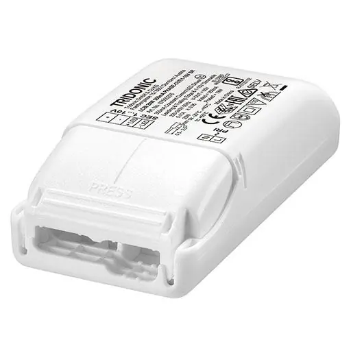
This independent dimmable LED driver provides constant current output. Key features include:
- Output current options: 350 mA or 500 mA
- Output power: 19 W
- Dimmable via leading/trailing edge phase dimmers or 1-10 V interface
- Protection class: IP20
- Nominal lifetime: up to 50,000 hours
- SELV (Safety Extra Low Voltage) compliant
Installation
Proper installation is critical for safety and performance. Follow these guidelines:
- Wiring Type: Use stranded wire with ferrules or solid wire (0.5 – 2.5 mm²).
- Stripping Length: Strip 4–5 mm for input and output terminals.
- Torque: Max torque at the clamping screw (M3) is 0.2 Nm.
- Strain Relief: It is recommended that the cable jacket diameter of the input side (D2) is 2 mm larger than the output side (D1).
- Wiring Guidelines: Keep mains leads separate from LED control gear (ideally 5–10 cm distance). Max length of output wires is 2 m.
Dimming
The driver supports two dimming methods:
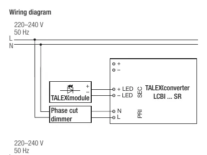
- Phase-cut: Compatible with leading and trailing edge dimmers.
- 1-10 V: Intensity varies proportionally to the signal. A logarithmic potentiometer is recommended.
- Warning: Do not connect both phase-cut and 1-10 V dimmers to the same device, as this may cause flicker.
Safety and Protection
The device includes built-in protection mechanisms:
- Overload protection: Automatically reduces output current if the voltage range is exceeded.
- Short-circuit protection: Switches off in case of a secondary side short circuit.
- No-load protection: Operates in burst mode to maintain constant output voltage if the LED string fails.
Maintenance
To replace an LED module:
- Switch off the mains power.
- Remove the LED module.
- Wait for 20 seconds.
- Connect the new LED module.
Note: Hot plug-in or secondary switching of LEDs is not permitted and may cause high current damage.
Technical Data
- Rated supply voltage: 220 – 240 V
- Ambient temperature (ta): -20 to +40 °C
- Max casing temperature (tc): 65 °C
- Dimensions: 101.5 x 51 x 29.5 mm
Manufacturer information
Tridonic
Practical help
Common problems
Flickering lights
Ensure that phase-cut and 1-10V dimmers are not connected to the same device simultaneously.
LED module failure
Wait at least 20 seconds after switching off mains power before replacing the LED module to prevent damage.
Wiring connection issues
Ensure the cable jacket diameter difference between input (D2) and output (D1) terminals is managed using the terminal flaps as recommended.
Before use
- Verify supply voltage is 220-240 V
- Ensure ambient temperature is between -20°C and +40°C
- Use wire cross-section of 0.5-2.5 mm²
- Strip wires to 4-5 mm length
- Ensure the installation location is dry and free of acid/oil
Show more Show less
Images and diagrams
- Wiring diagram shows separate connection paths for Phase-cut and 1-10V dimming configurations.
- Terminal layout diagram illustrates input (D2) and output (D1) connections with strain relief flaps.
Model compatibility
- Compatible with leading and trailing edge phase dimmers.
- Compatible with 1-10V dimmers (logarithmic potentiometer recommended).

Manual page author
David Miller
Documentation analyst