Lighting / Controllers & Dimmers
Installation Guide for Tridonic basicDIM ILD 16DPI 69f Control Module
A comprehensive installation and setup guide for the Tridonic basicDIM ILD 16DPI 69f control module. Includes wiring diagrams, sensor mounting instructions, motion detection settings, and technical specifications.
Quick answers from the manual
Quick answer
- The basicDIM ILD 16DPI 69f is a compact control module for DALI/DSI ballasts with integrated light and motion sensors. It requires professional installation and must be connected to a sensor to function. p. 1, 2
Key actions
- Mounting the sensor p. 1
- Adjusting zoom p. 1
First start
- Ensure the sensor is connected, power is off during installation, and wiring is separated to prevent interference. p. 1, 2
Problems and fixes
Incorrect presence detection
Check for heaters, fans, or office equipment in the detection zone.
p. 1, 2Technical specifications
| Parameter | Value | Meaning | Pages |
|---|---|---|---|
| Voltage | 220-240 VAC | Operating voltage | p. 1, 2 |
| Dimming | 1-100% | Dimming range | p. 1, 2 |
Where to find it in the PDF
- Installation and Technical Data p. 1, 2
Table of contents
Manual images
Click an image to enlargeQuick guide from the manual
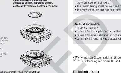
The Tridonic basicDIM ILD 16DPI 69f is a compact control module designed for DALI or DSI ballasts. Important: Installation must be performed by qualified specialist staff. The device cannot operate without a sensor. Ensure the power supply is switched off before handling the device.
Product Description
This module integrates an ambient light sensor and a motion sensor to control up to 10 DALI or DSI ballasts. It is designed for luminaire installation.
Safety Instructions
- Installation must be carried out by specialist staff with proven skills.
- Switch off the power supply before working on the device.
- Observe all relevant safety and accident prevention regulations.
- The device is not SELV compliant; standard mains voltage installation rules apply.
Installation
Wiring
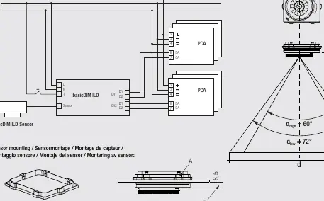
- Connect the DALI/DSI ballasts and switches according to the provided wiring diagram.
- Do not connect standard switches to the input; use push-to-make switches.
- Sensor wires must be routed separately from lamp and mains cables to prevent malfunctions. If separate routing is not possible, use shielded cables.
- The cable between the sensor and the base module must not be extended.
Sensor Mounting
- The sensor must be installed in the mounting box.
- Ensure all 6 snap-fits are engaged.
- To guarantee IP65 protection, the distance between the sensor surface and the luminaire surface must be less than 8.5 mm.
- The sensor can only be installed in the mounting box once (permanent snap-in).
Operation and Settings
Motion Detection and Zoom
- The lens can be adjusted for zoom (Low or High).
- Rotate the lens in the direction of the arrow until it stops at the desired position (High or Low).
- Note: Repeatedly adjusting the zoom (> 10 times) may impair the IP protection.
Detection Optimization
- Ensure the detection range lies within the lighting area of the controlled luminaires.
- Avoid overlapping detection ranges of multiple sensors.
- Keep heaters, fans, printers, and copiers out of the detection zone to prevent false presence detection.
- Install the sensor centrally in the luminaire to avoid direct light from lamps or reflections, which can distort measurement results.
Technical Data
- Nominal voltage: 220–240 VAC, 50/60 Hz
- Power loss: 2 W (standby 0.5 W)
- Dimming range: 1–100%
- Outputs: 2 DALI/DSI outputs (max. 10 ballasts)
- Operating temperature: 0 to +60 °C
- Protection (Controller): IP20
- Protection (Sensor): IP65 ready
Manufacturer information
Tridonic
Practical help
Common problems
Incorrect presence detection
Ensure heaters, fans, printers, or copiers are not located within the detection zone.
False light readings
Install the sensor centrally in the luminaire to avoid direct light from lamps or reflections from surfaces like metal shelves.
Lighting control malfunction
Ensure sensor wires are routed separately from lamp and mains cables. If not possible, use shielded cables.
Before use
- Verify installation is performed by qualified specialist staff.
- Ensure power supply is switched off.
- Confirm the sensor is connected (module will not function without it).
- Check that detection ranges of sensors do not overlap.
- Ensure the distance between sensor surface and luminaire is <8.5 mm for IP65.
Specs in practice
- Nominal voltage
- 220–240 VAC, 50/60 Hz.
- Dimming range
- 1–100% control capability.
- IP protection (Sensor)
- IP65 ready, provided the installation distance is <8.5 mm.
Images and diagrams
- Wiring diagram shows connection of sensor, switch, and DALI/DSI ballasts.
- Mounting diagram illustrates snap-fit installation and lens rotation for zoom adjustment.
Model compatibility
- Compatible with up to 10 DALI or DSI ballasts.
- Do not mix DALI and DSI ballasts on the same control gear.
- Not SELV compliant.

Manual page author
Michael Turner
Technical manual editor
Reviews PDF manuals for structure, safety notes, and practical product details so readers can find the right information quickly.