Lighting / LED Drivers
User Manual for Tridonic LED Driver LC 200W 24V o4a NF SC EXC2
Comprehensive user guide for the Tridonic LC 200W 24V LED driver. Includes installation instructions, wiring diagrams, dimming configurations, software setup, and technical specifications.
Table of contents
Manual images
Click an image to enlargeQuick Guide
The Tridonic LC 200W 24V o4a NF SC EXC2 is a dimmable constant voltage LED driver designed for flexible LED strips. It supports multiple control interfaces including DALI-2, DSI, switchDIM, and corridorFUNCTION. Configuration can be performed via NFC or DALI. Ensure the device is installed in a dry, oil-free, and acid-free environment with adequate ventilation.
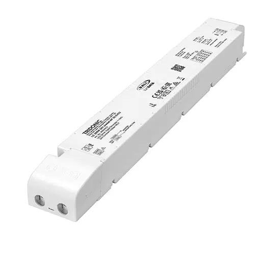
Product Overview
This driver is a 24V constant voltage unit with a maximum output of 200W. It features a compact design with strain relief and is suitable for independent use or luminaire installation. It includes an LTI (Lifetime Indicator) and supports lumDATA for energy reporting and diagnostics.
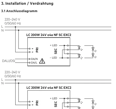
Installation and Wiring
Wiring Guidelines:
- Use stranded wire with ferrules (0.25–2.5 mm²) or solid wire (0.2–2.5 mm²) for the secondary side.
- Strip wires 9–10 mm for the secondary side and 8.5–9.5 mm for the primary side.
- Keep secondary wiring as short as possible to ensure good EMC performance.
- Secondary wiring must be kept separate from mains connections.
- Do not use secondary switching.
- The driver does not have secondary-side reverse polarity protection.
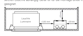
Installation Conditions:
- The device must not be covered with thermal insulation material.
- Maintain minimum clearance distances: >100 mm above and >20 mm on the sides.
- The device is not suitable for corner mounting.
Software and Programming
The driver supports configuration via the companionSUITE (deviceGENERATOR, deviceCONFIGURATOR, deviceANALYSER, 4service NFC app) and masterCONFIGURATOR. Data transfer is possible via NFC or the DALI control input.
Functions
- switchDIM: Allows direct connection of a standard push-button for dimming and switching. A short press toggles the light; a long press dims the light.
- corridorFUNCTION: Adjusts lighting based on occupancy when connected to a motion sensor.
- DC-Operation: Automatically detects DC voltage for emergency lighting systems and switches to a defined DC level.
- Enhanced Constant Light Output (eCLO): Maintains constant light flux over the lifetime of the LED module.
Protection Functions
- Intelligent Temperature Guard (ITG): Slowly reduces output power if the temperature exceeds defined limits.
- Intelligent Voltage Guard (IVG): Monitors mains voltage and indicates overvoltage by flashing the LEDs.
- Short Circuit/Overload Protection: The driver shuts down the output. A restart via mains reset or interface is required to reactivate.
Technical Specifications
- Output Voltage: 24 V
- Max Output Power: 200 W
- Dimming Range: 1–100%
- Protection Rating: IP20
- Lifetime: Up to 100,000 hours
- Ambient Temperature: -25 to +70°C (depending on load)
Manufacturer information
Tridonic
Practical help
Common problems
LED output does not activate after connection.
Restart the device via mains reset or interface (DALI, DSI, switchDIM) to activate the output.
Communication issues with NFC.
Ensure the antenna is placed directly on the driver. Remove any material between the driver and the antenna.
Device shuts down due to short circuit or overload.
The device will shut down. Perform a restart via mains reset or interface to reactivate.
Before use
- Verify input voltage is 220-240V.
- Ensure LED module is compatible with 24V constant voltage.
- Check wiring cross-section (0.2-2.5 mm²).
- Ensure proper strain relief is installed.
- Verify ambient temperature is within limits (-25 to +70°C depending on load).
Images and diagrams
- Wiring diagrams show connections for DALI/DSI and switchDIM.
- Installation diagrams indicate minimum clearance distances (>100mm, >20mm).
Model compatibility
- Compatible with DALI-2, DSI, switchDIM, and corridorFUNCTION.
- Not suitable for covering with thermal insulation material.

Manual page author
Emily Carter
User documentation editor
Prepares concise manual descriptions and highlights the most useful setup, operation, and maintenance information for readers.