Lighting / LED Drivers
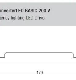
User Manual for Tridonic EM converterLED BASIC 200 V Emergency Lighting LED Driver
Comprehensive user guide for the Tridonic EM converterLED BASIC 200 V emergency lighting LED driver. Includes installation instructions, wiring diagrams, duration settings, and technical specifications.
Table of contents
Manual images
Click an image to enlargeQuick guide from the manual
The Tridonic EM converterLED BASIC 200 V is an emergency lighting LED driver designed for LED modules with a forward voltage of 50–200 V. Before installation, you must set the duration link (1 hour or 3 hours) as the device reads this setting only on the first power-up. Ensure the LED module forward voltage is within the specified range and that the battery is connected correctly.
Product description
This unit provides emergency lighting functionality for LED modules. It features a low-profile casing, automatic shutdown if the LED load is out of range, and constant power output. It is compatible with both dimmable and non-dimmable constant current LED drivers.
Installation and wiring
Proper wiring is critical for EMC compliance and safety. Keep LED leads as short as possible and separated from mains connections. The unit uses 3-pole technology for 2-pole LED module changeover and delayed power switching.
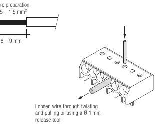
Wire preparation
Use solid wire with a cross-section of 0.5–1.5 mm². Strip 8–9 mm of insulation from the cables to ensure proper terminal operation. If you need to loosen a wire, twist and pull it, or use a 1 mm release tool.
Duration link selection
The device is supplied with the duration link in the 3-hour position. To set it for 1 hour, remove the link. Important: The link position is read only on the first power-up. If you change the link after installation, you must disconnect both the battery and mains supply for 10 seconds to reset the device; otherwise, it will indicate a false battery failure.
Technical data
- Rated supply voltage: 220–240 V, 50/60 Hz
- LED module forward voltage: 50–200 V
- Ambient temperature range: -5 to +55 °C
- Type of protection: IP20
- Maximum casing temperature: 70 °C
Safety and maintenance
The LED terminals, battery, indicator LED, and test switch terminals are classified as SELV (Safety Extra Low Voltage). Keep this wiring separated from mains input terminals. The test switch is used to check device function; press it for a minimum of 3 seconds to perform a test.
Manufacturer information
Tridonic
Practical help
Common problems
False battery failure indication
Occurs if the duration link is changed after installation without disconnecting battery and mains for 10 seconds. Perform a full power reset.
EMC interference
Ensure switched and unswitched supply wiring is routed as short as possible and kept far away from LED leads.
Before use
- Verify LED module forward voltage is between 50 V and 200 V.
- Set the duration link (1h or 3h) before connecting battery and mains.
- Ensure the battery type (NiCd or NiMH) is compatible.
- Check that the LED driver rating does not exceed the specified limits (e.g., 2.4 A peak output current).
- Prepare wires by stripping 8-9 mm of insulation.
Specs in practice
- Forward voltage (50-200 V)
- The required voltage range of the LED module to be compatible with this driver.
- Duration link
- A physical jumper that determines if the emergency light lasts for 1 hour or 3 hours.
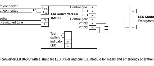
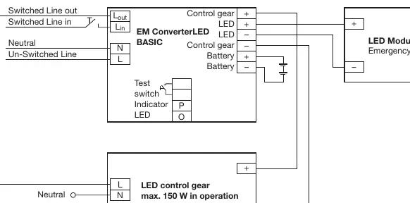
Images and diagrams
- Wiring diagrams show connections for non-maintained and maintained emergency operation.
- The diagrams illustrate how to connect the LED control gear, the EM converterLED module, and the LED module.
Model compatibility
- Compatible with most dimmable and non-dimmable constant current LED drivers.
- Max allowed output current of associated LED driver is 2.4 A peak.
- Max allowed inrush current of associated LED driver is 60 A peak for 1 ms.

Manual page author
Michael Turner
Technical manual editor
Reviews PDF manuals for structure, safety notes, and practical product details so readers can find the right information quickly.