Lighting / LED Drivers
Tridonic LLE 20x280mm 750lm LED Module User Guide
A comprehensive installation and technical guide for the Tridonic LLE 20x280mm 750lm LED module. Includes wiring diagrams, mounting instructions, thermal management requirements, and electrical specifications.
PDF source: Deutsch · summary: English
Table of contents
Manual images
Click an image to enlargeQuick Guide
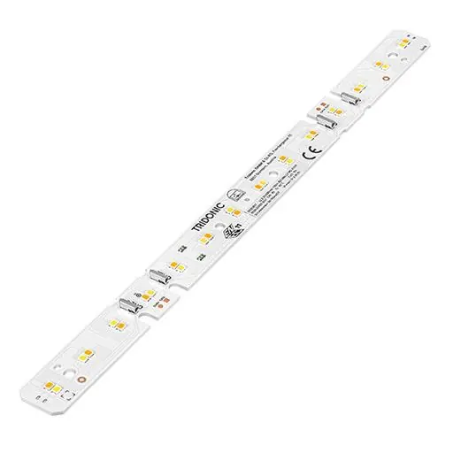
The Tridonic LLE 20x280mm LED module is a linear, tunable white LED component designed for professional lighting fixtures. It requires a constant current LED driver (SELV compliant) for operation. Proper thermal management is critical; the module must be mounted on a heatsink to maintain a tp-temperature of 55°C to ensure optimal performance and lifespan.
Installation and Wiring
The module must be operated with a constant current LED driver. Operating it with a constant voltage driver will cause irreversible damage. Ensure the driver provides the following protection functions: short-circuit detection, overload detection, and over-temperature shutdown.
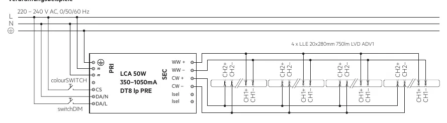
- Wiring Type: Use solid wire with a cross-section of 0.2 – 0.75 mm² (AWG24–18).
- Stripping Length: Strip the wires to 7.5 – 9.5 mm for proper connection in the push-in terminals.
- Polarity: Ensure correct polarity during wiring to avoid damage.
- Parallel Wiring: If wiring modules in parallel, ensure the total output current of the driver does not exceed 2.25 A. Only use modules with the same forward voltage bin (indicated on the module label).
Mounting Instructions
The module is designed for easy integration into linear luminaires.
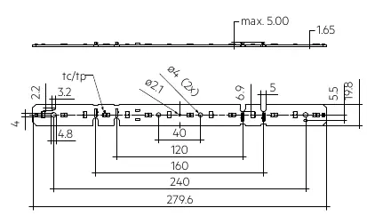
- Fastening: Use at least 4 M3 screws to mount the module.
- Torque: The maximum tightening torque for the screws is 0.5 Nm.
- Insulation: The module has basic insulation up to 60 V SELV. If the driver output voltage exceeds 60 V SELV, additional insulation (e.g., thermal foil) between the module and the heatsink is required.
- Mechanical Stress: Do not subject the module or its components to tension or pressure.
Thermal Management
The temperature at the tp-point is the decisive factor for the luminous flux and the lifespan of the LED module. A tp-temperature of 55°C must be maintained. Depending on the ambient temperature and the driver current, a heatsink is required to dissipate heat. Use thermal paste or thermal foil to ensure efficient heat transfer to the heatsink.
Safety and ESD
The module contains components sensitive to electrostatic discharge (ESD). Ensure proper ESD protection during manufacturing and installation. Avoid using solvent-based, condensation-curing, or acetate-curing adhesives, as well as materials containing sulfur, chlorine, or phthalates, as these can damage the LED module.
Manufacturer information
Tridonic
Practical help
Common problems
Module failure or reduced lifespan
Ensure the module is mounted on a heatsink to maintain a tp-temperature of 55°C. Check that the driver is a constant current type.
Damage to the module
Avoid polarity reversal during wiring. Ensure no solvent-based or sulfur-containing materials are used in the luminaire construction.
Brightness differences in parallel wiring
Ensure all modules in parallel have the same forward voltage bin (printed on the label) and that the driver current does not exceed 2.25 A.
Before use
- Verify the LED driver is a constant current type (SELV compliant).
- Ensure a suitable heatsink is prepared for thermal management.
- Prepare solid wires (0.2-0.75 mm²) stripped to 7.5-9.5 mm.
- Check that the mounting surface allows for M3 screw installation.
- Confirm ESD protection measures are in place.
Show more Show less
Specs in practice
- tp-temperature
- The reference temperature at the module's tp-point; must be kept at 55°C for optimal lifespan.
Images and diagrams
- The wiring diagram shows the connection of 4 modules to a single driver (LCA 50W) using a parallel configuration.
- The diagram illustrates the push-in terminal locations for CH1 and CH2 channels.
Model compatibility
- Requires constant current LED driver.
- Compatible with LEDiL DAISY-MINI lens system.
- Not compatible with constant voltage drivers.

Manual page author
Michael Turner
Technical manual editor