Industrial / Material Handling
User Manual for VEVOR Monorail Trolley 0.5T-H and 1T-H
Quick guide for VEVOR Monorail Trolley (0.5T-H, 1T-H). Includes installation steps, safety inspection, maintenance, and adjustment procedures for safe operation.
Table of contents
Manual images
Click an image to enlargeQuick guide from the manual
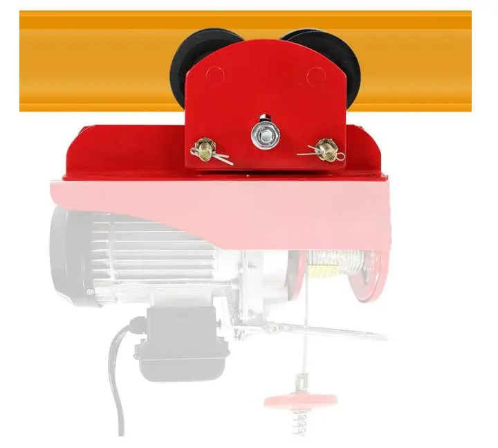
This manual provides instructions for the VEVOR Monorail Trolley, models 0.5T-H and 1T-H. These devices are designed to traverse a load along the bottom flange of an overhead I-beam or rail, converting a stationary hoist into a movable lifting system. Always ensure the trolley capacity matches your electric hoist and the load requirements.
Safety instructions
- Read all instructions carefully before operating.
- The trolley is intended for industrial use in ambient temperatures from 0 °F to 130 °F (-20 °C to +50 °C).
- Do not allow children to use or play with the appliance.
- Ensure the mounting structure has sufficient strength to support the load.
- Stop using the equipment immediately if any abnormality is detected.
- Always use the product according to its intended purpose to avoid injury.
Installation of trolley onto beam
There are two primary methods for installing the trolley:

- From the end of the beam: This is the preferred method. Slide the trolley onto the beam with the chain hoist coupled. After installation, ensure all nuts are correctly tightened and install travel limit stops (not provided) at the end of the runway.
- When space is limited: If there is no space at the end of the beam, remove the side plate from the suspension shaft. Place the side plate on the other side of the flange, reassemble, and reinstall the side plate. Securely bend the split pin of the shaft stopper pin and ensure all nuts are tightened.
Safety inspection
Perform the following checks before every use:
- Verify that the trolley and lifting equipment capacity are suitable for the job.
- Visually inspect the trolley for any damage or signs of poor maintenance.
- Slacken the suspension pin nuts and spread the side plates to slip the wheels over the beam.
- Screw the nuts firmly against the washers and secure them with lockouts.
- Suspend a light load to ensure all four wheels contact the runway beam.
- Suspend the maximum safe working load and run the unit slowly along the full length of the beam to ensure satisfactory operation.
- Check that the clearance between the beam's outer edge and the trolley wheel is equal on both sides.
- Ensure the load bar is assembled correctly and check for wear, defects, or corrosion.
Main structure
The trolley consists of the following key components:
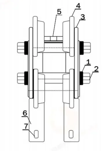
- Side Locking Nut
- Trolley Pin
- Side Plate
- Steel Wheel
- Casing Gaskets
- Bracket
- Mounting Hole
Maintenance and adjustment
When the trolley is coupled with a hoist, it must be adjusted using the adjusting spacers:
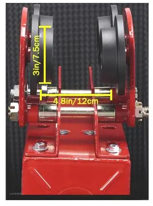
- Assemble the required number of spacer washers equally to the inside of the trolley side plates.
- The dimension between the Trolley Wheel Flanges should be about 1/4 inch (6mm) greater than the runway beam width.
- Assemble the nuts to the suspension pin after adjustment.
- Avoid prolonged exposure to the sun to prevent aging of materials.
Technical specifications
The trolley is designed for horizontal transport of loads by hand. Compatibility is as follows:
- 1100lbs trolley (0.5T-H): Suitable for PA200-PA500 electric hoists.
- 2200lbs trolley (1T-H): Suitable for PA600-PA1000 electric hoists.
- Adjust range: 2.68-4.33 inches.
Manufacturer information
VEVOR
Practical help
Common problems
Trolley does not fit the beam width.
Adjust the number of spacer washers on the suspension pin to ensure the wheel flange clearance is about 1/4 inch (6mm) greater than the runway beam width.
Trolley wheels do not contact the beam properly.
Suspend a light load to the trolley to ensure all four wheels contact the runway beam, then screw the nuts tightly against the washers and secure with lockouts.
Before use
- Check that the structure for mounting the trolley has sufficient strength.
- Verify the trolley and lifting equipment capacity are suitable for the job.
- Inspect the trolley for any damage or abnormal conditions.
- Ensure the load bar is assembled correctly.
- Check the load bar for wear, defects, or corrosion before every use.
Specs in practice
- Adjust range
- The width of the beam the trolley can accommodate (2.68-4.33 inches).
Images and diagrams
- The main structure diagram identifies the side locking nut, trolley pin, side plate, steel wheel, casing gaskets, bracket, and mounting hole.
- Maintenance images illustrate how to measure and adjust the spacing between trolley wheels using washers.
Model compatibility
- 1100lbs trolley is suitable for PA200-PA500 electric hoists.
- 2200lbs trolley is suitable for PA600-PA1000 electric hoists.

Manual page author
Emily Carter
User documentation editor
Prepares concise manual descriptions and highlights the most useful setup, operation, and maintenance information for readers.