HVAC / Heat Pumps
Wiring Diagram for Viessmann Vitocal 100-AW Heat Pump
Access the official wiring diagram and component guide for the Viessmann Vitocal 100-AW heat pump. This guide details electrical connections between the outdoor and indoor units, component identification, and essential safety warnings for...
Table of contents
Important Information
This document provides the official wiring diagram and component guide for the Viessmann Vitocal 100-AW heat pump (Model AM2V). It is intended for use by qualified technicians to understand the electrical connections between the Outdoor Unit (ODU) and the Indoor Unit (IDU).
Component Legend
The system utilizes various components for operation and monitoring. Key components identified in the diagram include:
- PHWC: DHW Recirculation Pump
- PHGC: Glycol Circuit Pump
- VCH: Cooling/Heating Diverting Valve
- PHC1 / PHC2: Heating Circuit 1 / 2 Pump
- TCH1 / TCH2: Heating Circuit 1 / 2 Temperature Sensor
- TCVL: DHW Tank Temperature Sensor
- TR: Room Temperature Sensor
- TO: Outdoor Temperature Sensor
- IOUT: Dry Contact Backup Heat Generator Activation
- F1 / F2 / F3: Fuses
Electrical Connections
The diagram illustrates the interface between the Outdoor Unit and the Indoor Unit. Connections are categorized into:
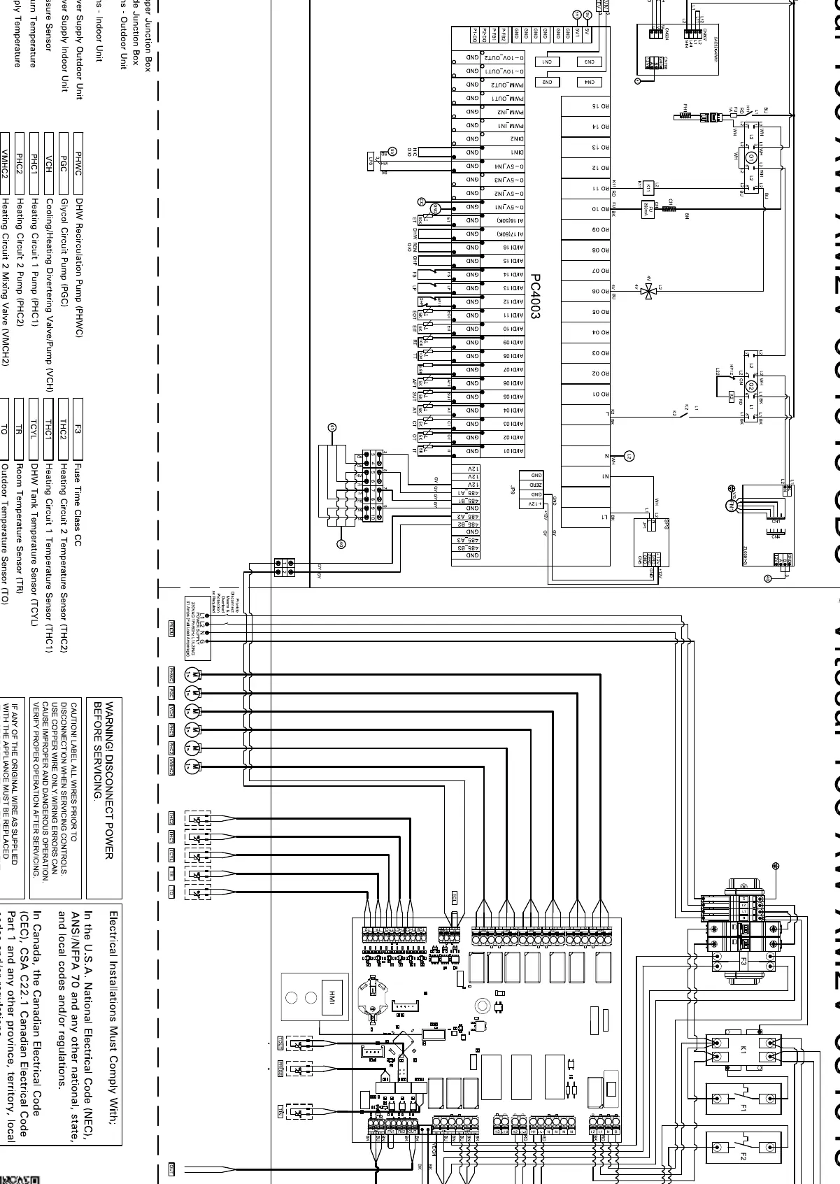
- Outdoor Unit Upper Junction Box: Main power and communication interface.
- Field Connections (Outdoor): Specific terminals for external sensors and pumps.
- Field Connections (Indoor): Terminals for indoor unit sensors and control signals.
Ensure that the 120 Ohm End of Line (EOL) Modbus resistor is correctly installed as indicated in the diagram to maintain communication integrity.
Safety and Compliance
Strict adherence to safety protocols is required when working with this equipment:
- Disconnect Power: Always disconnect all power sources before servicing the unit to prevent electrical shock.
- Compliance: Electrical installations must comply with the National Electrical Code (NEC) in the U.S.A., the Canadian Electrical Code (CEC) in Canada, and all applicable local codes and regulations.
- Replacement Parts: If any original wire is supplied, it must be replaced with its equivalent to maintain safety standards.
Manufacturer information
Viessmann Climate Solutions
Practical help
Common problems
System communication failure
Verify the installation of the 120 Ohm EOL Modbus resistor.
Incorrect sensor readings
Check wiring continuity and terminal connections for TCH1, TCH2, TCVL, TR, and TO sensors.
Before use
- Ensure all power is disconnected before servicing.
- Verify compliance with local electrical codes (NEC/CEC).
- Check all field connections between the ODU and IDU.
- Confirm the 120 Ohm Modbus resistor is installed if required.
- Inspect fuses F1, F2, and F3 for continuity.
Images and diagrams
- The diagram maps the electrical interface between the Outdoor Unit (ODU) and Indoor Unit (IDU).
- Connections are grouped into Field Connections (Outdoor) and Field Connections (Indoor).
- Specific terminals are provided for pumps, sensors, and valves.
Model compatibility
- Designed for Viessmann Vitocal 100-AW AM2V models.
- Requires compliance with NEC (USA) or CEC (Canada) standards.

Manual page author
Michael Turner
Technical manual editor
Reviews PDF manuals for structure, safety notes, and practical product details so readers can find the right information quickly.