Plumbing / Valves & Fittings
Installation and Maintenance Instructions for ZURN 1260XL Water Hammer Arrester
A comprehensive guide for installing and sizing the ZURN 1260XL Water Hammer Arrester. Includes instructions for branch lines, long pipe runs, fixture unit calculations, and maintenance requirements.
Table of contents
Manual images
Click an image to enlargeQuick Guide from the Manual
The ZURN 1260XL Water Hammer Arrester is designed to mitigate shock in water distribution systems. To ensure proper performance, follow these key steps:
- Flush lines: Always flush lines thoroughly before installation.
- Size correctly: Determine the required size (A through F) based on fixture units (Table II) and pipe length (Table III).
- Location: Install as close as possible to the source of shock.
- Seal: Use only Teflon tape on pipe threads.
- Installation: Use an appropriately sized wrench on the hex portion only.
Installation Instructions
Proper installation is critical for the device to function effectively. Ensure there is an unobstructed path to the arrester. When installing, use a wrench on the hex fitting to avoid damaging the body. If flow pressures are between 65 and 85 PSIG, select the next larger size arrester than what is indicated by the standard sizing charts.
Sizing and Selection
Sizing is based on standard fixture unit ratings used by engineers. Follow this process:
- Determine the total number of fixture units using the provided Fixture Units Sizing Information table.
- Determine the required shock arrester size (A-F) using Table I.
- Match the arrester to the size and length of the pipe run using Table III.
All sizing data assumes flow velocities of 10 F.P.S. or less.
Branch Line Rules
The placement of the arrester depends on the length of the branch line:
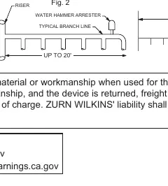
- Branch lines of 20 feet or less: Place the Water Hammer Arrester at the end of the branch line between the last two fixtures served.
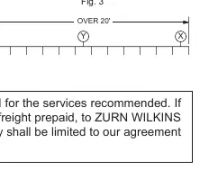
- Branch lines exceeding 20 feet: An additional Water Hammer Arrester is required. The sum of the fixture unit ratings of the two units must be equal to or greater than the demand of the branches.
Long Runs of Piping
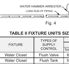
When piping is used to serve remote equipment, the Water Hammer Arrester should be located as close as possible to the point of quick closure (e.g., the valve or faucet). Ideally, flow pressure in branch lines should not exceed 55 PSIG. If pressure exceeds this, pressure-reducing valves should be installed.
Maintenance and Warranty
ZURN WILKINS valves are guaranteed against defects in material or workmanship for 12 months from the date of purchase when used for recommended services. If a defect develops, the device must be returned, freight prepaid, to ZURN WILKINS for repair or replacement.
Practical help
Common problems
Water hammer noise persists after installation
Verify that the arrester is sized correctly based on fixture units and pipe length. Ensure it is installed as close as possible to the source of the shock.
Leakage at the connection point
Ensure only Teflon tape was used to seal pipe threads. Do not overtighten or damage the hex fitting.
High pressure in branch lines
If flow pressure is between 65 and 85 PSIG, you must select the next larger size Water Hammer Arrester than the one indicated by standard charts.
Before use
- Flush all water lines thoroughly before installing the arrester.
- Calculate total fixture units using the provided sizing table.
- Determine the correct arrester size (A-F) based on fixture units.
- Check pipe length and diameter to select the appropriate model from Table III.
- Apply Teflon tape to pipe threads.
- Ensure an unobstructed path to the arrester.
Images and diagrams
- Fig 2: Shows placement for branch lines 20 feet or less (at the end of the line).
- Fig 3: Shows placement for branch lines exceeding 20 feet (requires additional arrester).
- Fig 4: Illustrates placement for long runs of piping to remote equipment, close to the quick closure valve.
Model compatibility
- Compatible with various supply controls including Flush Valves, Flush Tanks, and Faucets.
- Sizing tables differentiate between Public and Private fixture unit requirements.

Manual page author
Michael Turner
Technical manual editor
Reviews PDF manuals for structure, safety notes, and practical product details so readers can find the right information quickly.