Plumbing / Valves & Fittings
Installation Guide for Danfoss SSM Stainless Steel Manifold
Quick installation and configuration guide for the Danfoss SSM Stainless Steel Manifold. Includes dimensional data, circuit configuration tables, and flow balancing charts for underfloor heating systems.
Table of contents
Manual images
Click an image to enlargeQuick guide from the manual
This document provides essential dimensional data and flow balancing information for the Danfoss SSM Stainless Steel Manifold. It is intended for professional installers setting up underfloor heating systems. The guide focuses on determining the correct manifold length based on the number of circuits and configuring flow settings according to pipe dimensions and circuit lengths.
Dimensional data
The SSM Stainless Steel Manifold is available in various configurations ranging from 2+2 to 12+12 circuits. The total length (L1) of the manifold depends on the number of circuits installed. Ensure you have sufficient space for the installation based on the following dimensions:
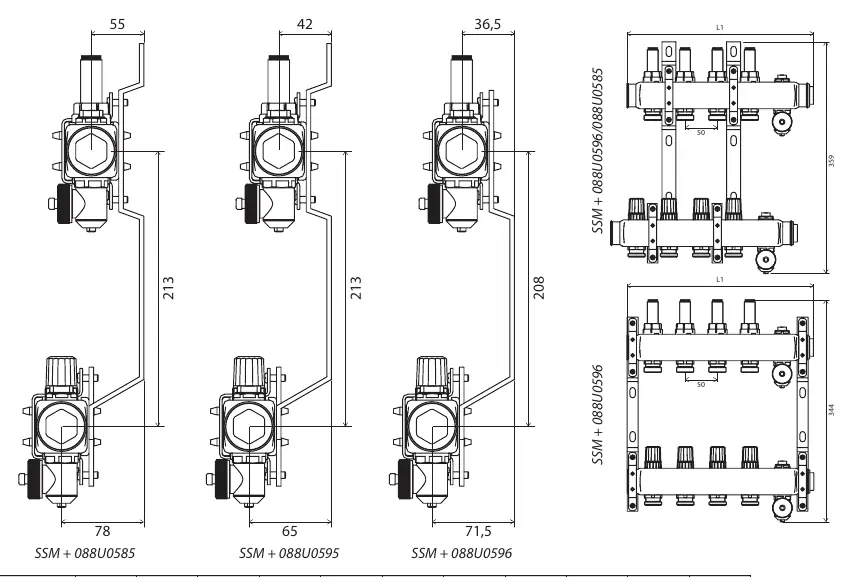
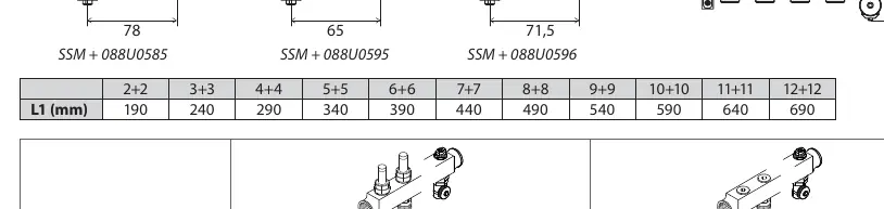
- 2+2 circuits: 190 mm
- 3+3 circuits: 240 mm
- 4+4 circuits: 290 mm
- 5+5 circuits: 340 mm
- 6+6 circuits: 390 mm
- 7+7 circuits: 440 mm
- 8+8 circuits: 490 mm
- 9+9 circuits: 540 mm
- 10+10 circuits: 590 mm
- 11+11 circuits: 640 mm
- 12+12 circuits: 690 mm
System configuration and balancing
To ensure efficient operation of the underfloor heating system, the flow must be balanced based on the specific pipe diameter and the length of each heating circuit. The manual provides reference tables for two common pipe sizes:
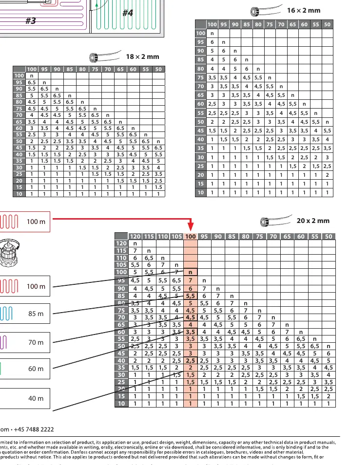
- 16 x 2 mm pipes: Use the corresponding table to find the flow setting based on circuit length (10m to 100m).
- 20 x 2 mm pipes: Use the corresponding table to find the flow setting based on circuit length (10m to 120m).
Locate the intersection of your circuit length and pipe diameter in the provided tables to determine the required setting for the manifold flow meter.
Manufacturer information
Danfoss A/S
Practical help
Common problems
Incorrect flow distribution
Ensure the flow meters are adjusted according to the specific pipe length and diameter tables provided in the manual.
Insufficient installation space
Verify the total manifold length (L1) against the number of circuits (2+2 to 12+12) before mounting.
Before use
- Identify the number of heating circuits (2+2 to 12+12).
- Confirm the pipe diameter (16x2mm or 20x2mm).
- Measure the length of each individual heating circuit.
- Check available wall space against the L1 dimension table.
- Consult the flow balancing tables to determine settings for each circuit.
Specs in practice
- 16 x 2 mm / 20 x 2 mm
- The outer diameter and wall thickness of the heating pipes, which dictates the flow balancing requirements.
Images and diagrams
- The dimensional drawings show the vertical and horizontal spacing requirements for different manifold configurations.
- The flow/pressure drop charts illustrate the relationship between flow rate (Q) and pressure drop (dp) for system calibration.
Model compatibility
- Designed for underfloor heating systems.
- Compatible with 16x2mm and 20x2mm pipe sizes.

Manual page author
Emily Carter
User documentation editor
Prepares concise manual descriptions and highlights the most useful setup, operation, and maintenance information for readers.