Computers / Laptops
Installation Guide for LG Gas Piping Kit (024-300S Series)
Official installation instructions for LG Gas Piping Kits used on LG/LD/KG/KD 024-300S packaged gas units. Includes component lists, pressure requirements, and detailed piping diagrams for various unit models.
Table of contents
Manual images
Click an image to enlargeImportant Information for Installation
This document provides installation instructions for the Gas Piping Kit designed for LG/LD/KG/KD 024-300S packaged gas units. Installation and service must be performed by a qualified installer, service agency, or the gas supplier. Improper installation can result in property damage, personal injury, or loss of life.
Installation Requirements
- Local Codes: Before connecting piping, consult with the local gas company or authorities having jurisdiction to ensure compliance with local codes.
- Pipe Sizing: When determining pipe size, consider the length of the run from the gas meter to ensure a maximum pressure drop of 0.5" w.c. (0.12 kPa). Do not use a supply pipe smaller than the unit gas connection.
- Threaded Joints: Compounds used on threaded joints must be resistant to the action of liquefied petroleum gases.
- Power and Gas: Ensure all power and gas supply to the unit are turned off before beginning installation.
Operating Pressure Requirements
Ensure the operating pressure at the unit gas connection meets the following specifications:
- Natural Gas Units: Minimum 4.5" w.c. (1.19 kPa) for 024-072 units; Minimum 4.7" w.c. (1.17 kPa) for 090-300S units. Maximum pressure is 10.5" w.c. (2.60 kPa).
- LP/Propane Gas Units: Minimum 11" w.c. (2.74 kPa); Maximum 13.0" w.c. (3.24 kPa).
Installation Steps
- Verify the kit contents against the Shipping and Packing List provided in the manual.
- Identify the correct piping diagram for your specific unit model using the provided table.
- Complete the gas piping installation as shown in the corresponding figure.
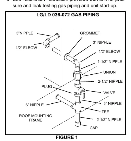
- Perform pressure and leak testing on the gas piping and unit start-up according to the installation instructions provided with the main unit.
Piping Diagrams
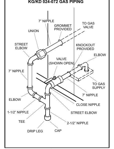
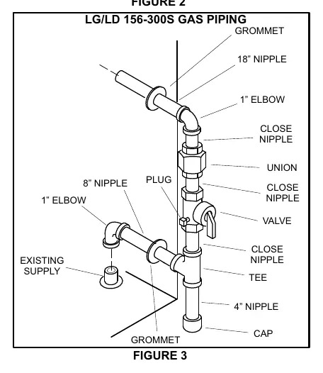
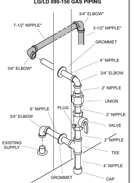
Refer to the specific figures for your unit model to ensure correct component placement, including nipples, elbows, unions, valves, and grommets.
Manufacturer information
LG Electronics
Practical help
Common problems
Improper gas pressure
Ensure pressure at the unit gas connection is within the specified range (4.5-10.5" w.c. for Natural Gas; 11-13" w.c. for LP/Propane).
Excessive pressure drop
Verify pipe size based on the length of the run from the gas meter. Do not use supply pipe smaller than the unit gas connection.
Before use
- Verify local code requirements with the gas company or local authorities.
- Ensure all power and gas supply to the unit are turned off.
- Confirm the correct kit is being used for the specific unit model (refer to Table 1).
- Check that all components from the packing list are present.
- Ensure thread compounds are resistant to liquefied petroleum gases.
Specs in practice
- Natural Gas Pressure
- Operating pressure at unit connection must be 4.5"-10.5" w.c. (varies by unit size).
- LP/Propane Pressure
- Operating pressure at unit connection must be 11"-13" w.c.
- Pressure Drop
- Maximum allowable pressure drop is 0.5" w.c. (0.12 kPa) from the gas meter.
Images and diagrams
- Figure 1: Piping configuration for LG/LD 036-072 units.
- Figure 2: Piping configuration for KG/KD 024-072 units.
- Figure 3: Piping configuration for LG/LD 156-300S units.
- Figure 4: Piping configuration for LG/LD 090-150 units.
Model compatibility
- Kit LB-95299A: Used for LG/LD 036-072.
- Kit LB-95299H: Used for KG/KD 024-072.
- Kit LB-95299B, F: Used for LG/LD 078-150.
- Kit LB-95299C, G: Used for LG/LD 156-300S.

Manual page author
David Miller
Documentation analyst
Organizes user manual content into clear summaries, with attention to model details, product context, and everyday usability.