Industrial / Circuit Breakers
User Manual for AEG VB Vacuum Circuit Breaker
Comprehensive user guide for the AEG VB Vacuum Circuit Breaker. Includes installation, operation, maintenance, technical specifications, and troubleshooting procedures.
Quick answers from the manual
Quick answer
- The AEG VB Vacuum Circuit Breaker is a 36/40.5kV protection and control device for industrial and power applications. It features a spring energy storage mechanism and is designed for modular, reliable operation. p. 5
Key actions
- Energy storage operation p. 8
- Closing operation p. 8
First start
- Installation and commissioning p. 14, 15
Problems and fixes
Failure to close
Check closing position, handcart position, auxiliary supply, and secondary circuit.
p. 15Maintenance and reset
- Maintenance intervals p. 16
Technical specifications
| Parameter | Value | Meaning | Pages |
|---|---|---|---|
| Rated voltage | 36/40.5 kV | Operating voltage | p. 9 |
| Rated normal current | 630/1250/1600/2000/2500/3150 A | Current capacity | p. 9 |
Where to find it in the PDF
- Technical Parameters p. 9, 10
- Wiring Diagrams p. 16, 17, 18
Table of contents
Manual images
Click an image to enlargeQuick guide from the manual
The AEG VB Vacuum Circuit Breaker is designed for 36/40.5kV power systems. It is intended for use as protection and control equipment in industrial and mining enterprises, power plants, and substations. Important: All installation, operation, and maintenance must be performed by professionally trained, full-time electrical personnel. Ensure the equipment is used within its rated parameters and under normal indoor environmental conditions.
Operating mechanism
The circuit breaker utilizes a spring energy storage mechanism. Energy storage can be performed manually or via a motor:
- Manual storage: Insert the energy storage handle into the manual energy storage shaft and shake it clockwise until the indicator shows the spring is charged.
- Motor storage: The motor automatically charges the spring when power is connected.
- Closing: Press the "closing" button or use remote operation to trigger the closing coil.
- Opening: Press the "opening" button or connect the external power supply to the opening coil.
Propulsion mechanism
For withdrawable types, the handcart must be correctly positioned within the switch cabinet:
- Cabinet entry: Close the interlocking piece valve, set handles to position B, and push the handcart until pins correspond to positioning holes.
- Working position: Use the operating handle to advance the handcart. A "click" sound indicates the clutch has slipped, meaning the handcart is in position.
- Emergency opening: Use the emergency opening handle (rotate counterclockwise) if required.
Installation and commissioning
When lifting the circuit breaker, use the designated lifting points. Ensure the upper and lower outlet arms are not stressed during movement. Before commissioning, verify the connection status of the primary circuit, secondary circuit, and grounding body. Perform a manual operation test to ensure the mechanism functions correctly.

Maintenance
The circuit breaker is largely maintenance-free during normal use due to its durable design. However, periodic inspections are required:
- 5-year inspection: Check grease on bearings, verify component function, and perform a comprehensive appearance inspection.
- 10-year maintenance: Re-apply grease to supporting shafts and bearings, check fasteners for looseness, and review the operating mechanism.
- Cleaning: Clean dust from insulating parts using a dry cloth. Use household alkaline cleaning agents if necessary, but avoid carbon tetrachloride or trichloroethylene.
Safety and storage
Always disconnect auxiliary power before maintenance. Store the circuit breaker in a dry, well-ventilated room at temperatures not lower than -25°C. Protect the unit from dust and moisture during storage.
Manufacturer information
AEG Powertools
Practical help
Common problems
Failure to close
Check if the breaker is in the closing position, verify the handcart is fully in the operation or test position, ensure the closing locking device is not active, and check that the auxiliary supply meets specifications.
Handcart cannot be pushed in or pulled out
Ensure the breaker is in the opening state, the pushing handle is fully inserted, the mechanism is at the test position, and the cabinet earthing interlocking is released.
Before use
- Verify ambient temperature is between -25°C and +40°C.
- Ensure altitude is ≤ 1000m.
- Confirm no inflammable, explosive, or corrosive gases are present.
- Ensure all auxiliary power supplies are connected correctly according to the wiring diagram.
- Verify the circuit breaker is in the open state before installation.
Specs in practice
- Rated voltage
- 36/40.5 kV operating voltage range.
- Rated normal current
- Available in 630A to 3150A configurations.
- Rated frequency
- Compatible with 50/60 Hz systems.
- Classification
- E2-M2-C2 class rating for electrical and mechanical endurance.
Images and diagrams
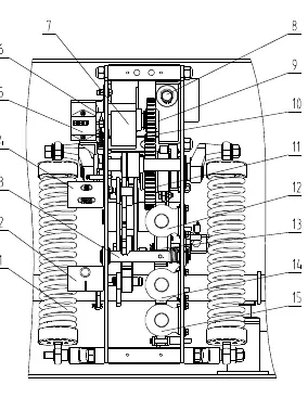
- Fig 1: Front view of the operation mechanism showing the charging motor, springs, and indicators.
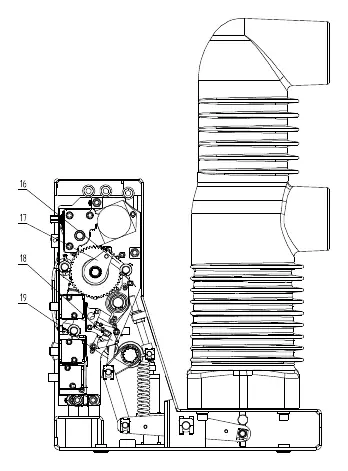
- Fig 2: Side view of the operating mechanism showing interlock blocks.
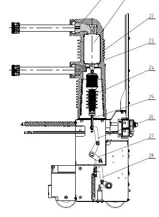
- Fig 3: Internal structure diagram showing terminals, vacuum chamber, and pull rods.
Model compatibility
- Complies with GB/T 1984, IEC 62271-100, and IEC 60694 standards.

Manual page author
David Miller
Documentation analyst
Organizes user manual content into clear summaries, with attention to model details, product context, and everyday usability.