Industrial / Circuit Breakers
User Manual for AEG VL Vacuum Circuit Breaker
Comprehensive user manual for the AEG VL Vacuum Circuit Breaker. Includes detailed installation instructions, operating procedures, maintenance schedules, technical specifications, and electrical schematics for safe and efficient use.
Quick answers from the manual
Quick answer
- The AEG VL Vacuum Circuit Breaker is an indoor protection and control unit. This manual covers installation, operation, maintenance, and technical specifications for the 2025IM6701 series. p. 1, 5
Key actions
- Perform manual operation test p. 22
- Conduct maintenance every 5 years p. 23
First start
- Ensure normal indoor environmental conditions and perform a manual operation test. p. 5, 22
Problems and fixes
Failure to close
Check breaker state, handcart position, auxiliary supply, and secondary circuit.
p. 22Maintenance and reset
- Cut off energy storage power supply and operate to close/open once to release energy before maintenance. p. 23
Technical specifications
| Parameter | Value | Meaning | Pages |
|---|---|---|---|
| Rated voltage | 12 / 24 / 40.5 kV | Operating voltage range | p. 9 |
| Rated frequency | 50/60 Hz | Operating frequency | p. 9 |
Where to find it in the PDF
- Technical Parameters p. 9, 10
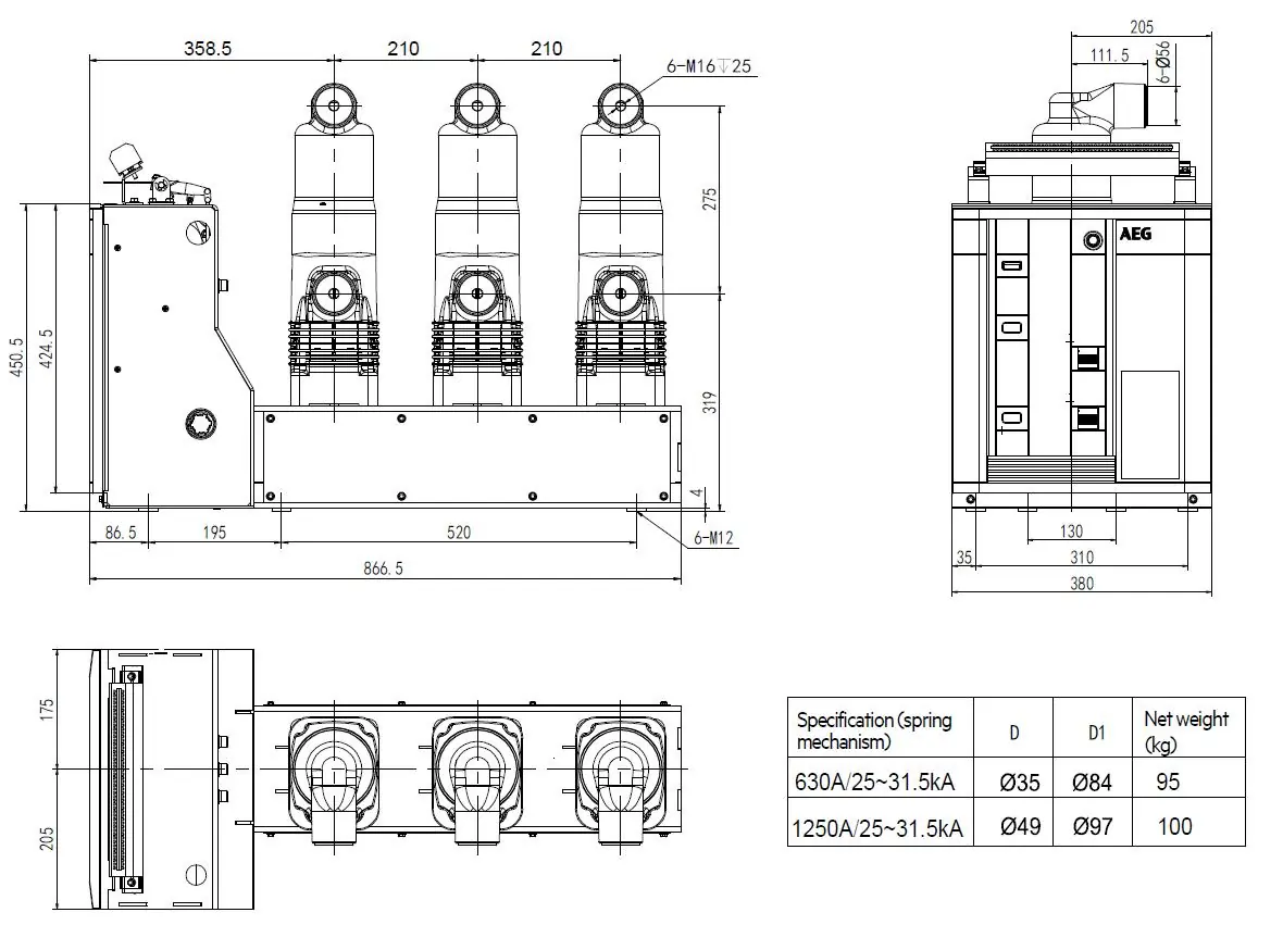
- Dimensions p. 11, 12, 13, 14
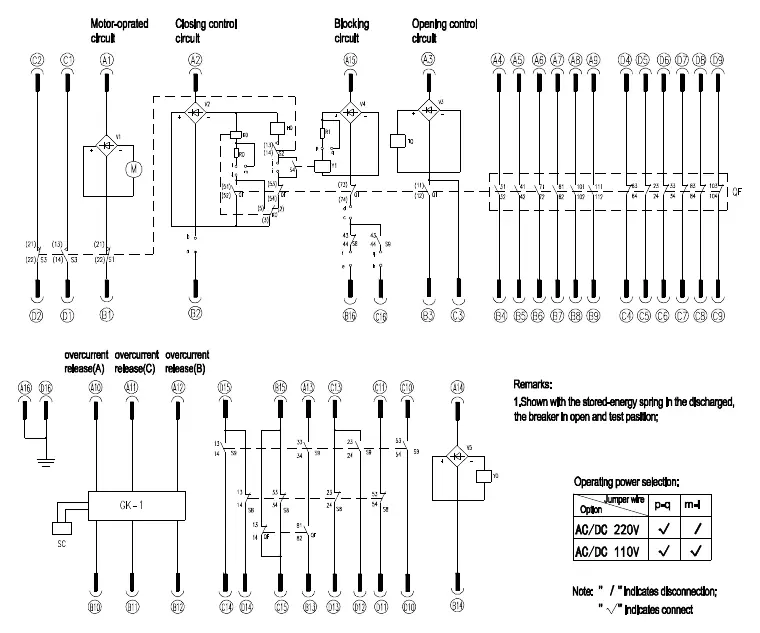
- Electrical Schematics p. 19, 20, 21
Table of contents
Manual images
Click an image to enlargeQuick Guide
This manual provides essential information for the installation, operation, and maintenance of the AEG VL Vacuum Circuit Breaker. Safety is paramount: all operations and maintenance must be performed by professionally trained electrical personnel. Ensure the equipment is used within normal indoor environmental conditions and never operate beyond rated parameters.
Overview and Structural Principle
The VL vacuum circuit breaker is designed for indoor air-insulated switchgear components, serving as a protection and control unit for power grids and industrial enterprises. The conductive circuit is fixed within insulating parts to prevent external impact and pollution. The operating mechanism utilizes a spring energy storage system, which can be charged manually or via an electric motor.
Installation and Commissioning
When installing the circuit breaker, ensure it is not subject to tension or deformation. Use disc spring gaskets at bottom mounting points. When connecting the main terminal, avoid permanent tension or pressure. For handcart-type breakers, ensure the unit is pushed into the switch cabinet correctly, turning the handle at medium speed until the "click" of the position switch is heard.

Operation
The breaker supports both manual and remote operation. Energy storage is required for closing; this can be done via the motor or the manual energy storage handle. The breaker features an anti-misoperation interlock system to prevent unsafe operations, such as closing when the breaker is already closed or when the handcart is not in the correct position.
Maintenance
The circuit breaker is generally maintenance-free during normal use. However, periodic inspections are required based on operation time (e.g., every 5 years or after a specified number of operations). Maintenance includes checking grease on bearings, verifying component function, and inspecting fasteners. Always disconnect auxiliary power supplies before performing any maintenance.
Troubleshooting
If the breaker fails to close, check if it is already in the closing position, verify the handcart position, ensure the closing locking device is not engaged, and check the secondary circuit. If the handcart cannot be moved, ensure the breaker is in the open position, the handle is fully inserted, and the earthing interlock is released.
Manufacturer information
AEG Powertools
Practical help
Common problems
Failure to close
Check if the breaker is already closed, verify the handcart is in the correct position, ensure the auxiliary supply is connected and sufficient, and check the secondary circuit.
Handcart cannot be pushed in or pulled out
Ensure the breaker is in the open position, the pushing handle is fully inserted, the pushing mechanism is correctly placed at the test position, and the cabinet earthing interlock is released.
Before use
- Verify the environment meets normal indoor conditions (temperature -25°C to +40°C, humidity ≤95%).
- Ensure all auxiliary power supplies are connected correctly.
- Check the connection status of the primary circuit, secondary circuit, and grounding body.
- Perform a manual operation test before putting into service.
- Ensure the circuit breaker is free from damage or contamination.
Specs in practice
- Rated voltage
- The maximum voltage the circuit breaker is designed to handle (12kV, 24kV, or 40.5kV).
- Rated normal current
- The continuous current the breaker can carry (ranges from 630A to 5000A depending on model).
- Rated short-circuit breaking current
- The maximum short-circuit current the breaker can safely interrupt.
Images and diagrams
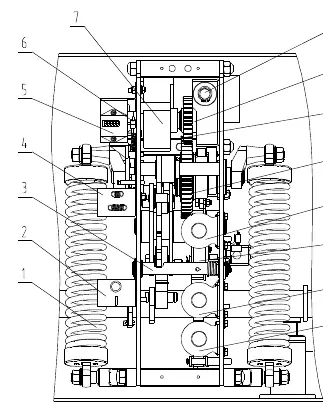
- Fig. 1: Front view of the operation mechanism showing the location of coils, motors, and indicators.
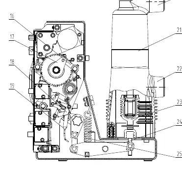
- Fig. 2: Side view of the operation mechanism showing the vacuum chamber and interlock blocks.
- Fig. 3-5: Electrical schematic diagrams for withdrawable and fixed types.
Model compatibility
- Designed for indoor use only.
- Not suitable for environments with inflammable/explosive hazards, corrosive gas, or violent vibration.
- Earthquake intensity must not exceed Level 8.

Manual page author
Emily Carter
User documentation editor
Prepares concise manual descriptions and highlights the most useful setup, operation, and maintenance information for readers.