General / Other Manuals
AKO-17630 and AKO-17631 PROCool Electronic Panel User Guide
Comprehensive installation, operation, and maintenance guide for the AKO PROCool electronic panels (models 17630 and 17631), including technical specifications and safety recommendations.
Table of contents
Product Overview
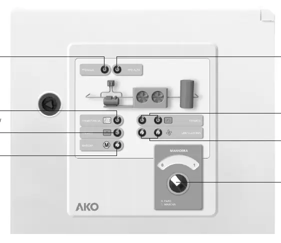
The AKO PROCool electronic panels (models AKO-17630 and AKO-17631) are designed for professional HVAC and air conditioning control. The front panel features a clear interface with indicators for low and high pressure switches, compressor thermistors, thermal relays, and running status. Model AKO-17631 includes additional indicators for fan thermal relays and fan operation. A central Stop/Run selector allows for easy system control.
Technical Specifications
- Rated Voltage: 400V AC (Un) or 230V AC (Ue) at 50/60 Hz.
- Maximum Nominal Input Current: 32 A.
- Degree of Protection: IP65.
- Operating Temperature: -5 ºC to 40 ºC.
- Dimensions: 400x300x165 mm (AKO-17630) and 500x400x175 mm (AKO-17631).
- Compliance: EN 61439-1, EN 61439-3, and EN-60730.
Safety and Installation
Installation must be performed by authorized personnel in accordance with current standards. Always disconnect the power supply before performing any work inside the panel. Ensure the panel is installed in a clean area without obstacles. The panel must be kept closed during operation. Earthing must be carried out outside the panel. Use only copper conductors for external connections.
Start-up and Maintenance
Before starting, verify that there are no loose parts, dust, or dampness inside the unit. Ensure all power connections are tightened and motor guards are correctly set. During start-up, monitor for electric arcs, overheating, or unusual noises from contactors. After the first 24 hours, re-tighten all power connections. Preventive maintenance includes annual inspection of switchgear wear and re-tightening of connections. Clean the exterior with a soft cloth and mild detergent; avoid abrasive chemicals or solvents.
Troubleshooting and Wiring
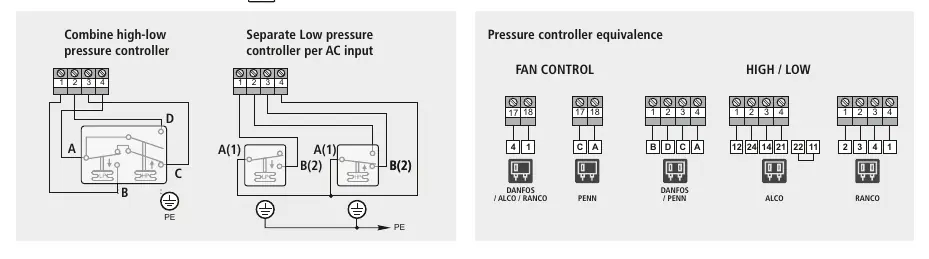
If issues arise, verify the power supply and check for overheating components. The system supports various pressure switch configurations, including combined high-low pressure controllers and separate low-pressure controllers per AC input. Refer to the provided wiring diagrams for specific controller compatibility, including Danfoss, Alco, Ranco, and Penn models.
Related manuals
Related manuals from the same brand or category.
General / Other Manuals
AKO 1652H4A11 Advanced Temperature Controller for Cold Rooms
AKOGeneral / Other Manuals
AKO-16526A / AKO-16526AN Advanced Temperature Controller
AKOGeneral / Other Manuals
AKO 16526A V2 Advanced Temperature Controller
AKOGeneral / Other Manuals
AKO-15724/AKO-15725 Temperature Data Logger
AKO
Manual page author
Emily Carter
User documentation editor
Prepares concise manual descriptions and highlights the most useful setup, operation, and maintenance information for readers.