Lighting / Fixtures
User Manual for Allen + Roth 11-Inch LED Flushmount Light
Quick guide for the Allen + Roth 11-Inch LED Flushmount Light with Motion Sensor. Includes installation steps, wiring diagrams, operating modes, and troubleshooting.
Table of contents
Manual images
Click an image to enlargeImportant Information
This light fixture requires 120-volts AC. All wiring must be in accordance with the National Electrical Code. Turn off power at the circuit breaker before installation or maintenance. Do not connect to dimmers or timers. The fixture is rated for 100 Watts total, with a sensor capacity of 360 Watts.
Product Description
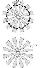
The Allen + Roth 11-Inch Flushmount Light features a built-in motion sensor with a 360-degree sensing angle and up to 30 ft. range. It supports multiple operating modes including Test, Auto, Accent, and Manual.
Installation
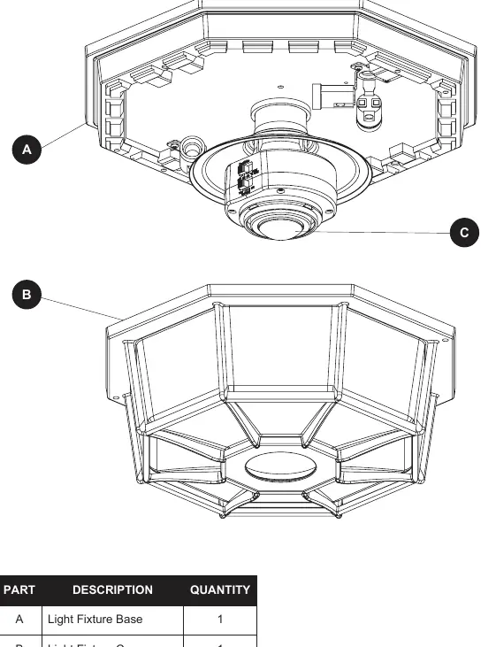
- Remove the two decorative nuts (BB) from the light fixture cover to separate it from the base.
- Remove the two decorative nuts (BB) to release the mounting plate (EE) from the base.
- Attach the mounting plate (EE) to the junction box using the mounting plate screws (AA).
- Wire the fixture according to the wiring diagrams (see Wiring section).
- Connect fixture wires to junction box wires using wire connectors (CC).
- Secure the grounding wire using the green ground pigtail and the GND screw on the mounting plate (EE).
- Slide the fixture onto the fixture mounting screws (DD) and secure with decorative nuts (BB).
- Install four candelabra base light bulbs (25 Watts maximum each, dimmable).
- Replace the light fixture cover and tighten the decorative nuts (BB).
Optional Wiring
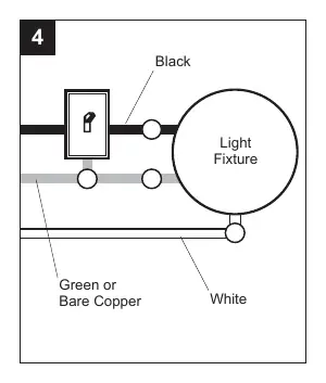
Wiring Diagram 1 (Standard): Connect the motion sensor's red wire to the standard light's black wire. Connect all white wires together.
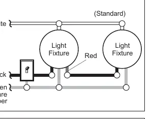
Wiring Diagram 2 (Primary/Controlled): Strip the red wire in both fixtures. Connect the red wire of the controlling (Primary) fixture to the red and black wires of the controlled fixture. Connect all white wires together.
Wiring Diagram 3 (Primary/Primary): Strip the red wire in both fixtures. Connect the red wire of one fixture to the red wire of the second fixture. Connect all white and black wires together.
Operating Instructions
Testing: Set the ON-TIME switch to TEST. The light will stay on for 5 seconds after motion stops. Ensure the Auto Bright control is set to OFF and sensitivity (SENS) is set to the '-' position.
Modes:
- Test: 5 seconds duration.
- Auto: 1, 5, or 10 minutes duration.
- Accent: 3, 6 hours, or dusk-to-dawn.
- Manual: Dusk-to-dawn (resets to Auto at dawn).
Sensitivity (SENS): Adjust toward '+' to increase detection zone or '-' to decrease it.
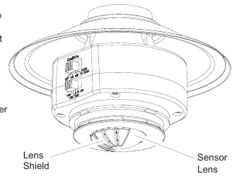
Coverage Area: The sensor detects heat movement. If false triggering occurs, install the included lens shield to block specific areas.
Care and Maintenance
Clean with clear water and a soft damp cloth only. Do not use paints, solvents, or chemicals. Do not spray with a hose or power washer.
Troubleshooting
If the light does not come on, check the light switch, bulb, fuse/circuit breaker, and wiring. If the light comes on in daylight, ensure it is not in TEST mode. If the light stays on continuously, check for heat sources (vents, animals) or ensure it is not in Manual or Auto Bright mode.
Specifications
- Power: 120 VAC, 60 Hz
- Electrical Load: 100 Watt Maximum total, 25 Watt Maximum per lamp holder
- Bulb Type: Candelabra Base, Type B, 25 Watt Maximum, Dimmable
- Sensing Range: Up to 30 ft. (9.1 m)
- Sensing Angle: Up to 360°
Manufacturer information
Allen + Roth
Practical help
Common problems
Lights will not come on
Check if the switch is off, bulb is loose/burned out, fuse is blown, or if daylight turn-off is in effect. Verify wiring.
Lights come on in daylight
Ensure the light control is not in TEST mode.
Lights stay on continuously
Check for heat sources like vents or animals. Ensure the unit is not in Manual or Auto Bright mode.
Lights flash on and off
This is normal if the unit is in TEST mode and warming up.
Before use
- Turn off power at the circuit breaker.
- Verify all parts are present (Base, Cover, Sensor, Hardware).
- Ensure you have required tools: screwdrivers, pliers, wire strippers, multi-meter, electrical tape, ladder.
- Do not connect to dimmers or timers.
Specs in practice
- Electrical Load
- 100 Watt Maximum total, 25 Watt Maximum per lamp holder.
- Sensing Range
- Up to 30 ft. (9.1 m) depending on temperature.
- Power Requirements
- 120 VAC, 60 Hz.
Images and diagrams
- Wiring Diagram 1: Standard motion light control.
- Wiring Diagram 2: Primary/Controlled setup for multiple lights.
- Wiring Diagram 3: Primary/Primary setup where either light triggers both.
Model compatibility
- Do not connect to dimmers or timers.
- Bulbs must be Candelabra Base, Type B, 25 Watt Maximum, Dimmable.

Manual page author
Emily Carter
User documentation editor
Prepares concise manual descriptions and highlights the most useful setup, operation, and maintenance information for readers.