Lighting / Fixtures
Instruction Manual for BEGA 24437 Wall Washer Light
Quick guide for the BEGA 24437 wall washer light. Includes installation steps, wiring instructions, technical specifications, and maintenance guidelines.
PDF source: Français · summary: English
Quick answers from the manual
Quick answer
- The BEGA 24437 is a wall washer light with symmetrical light distribution, IP65 protection, and DALI control capabilities. It requires installation by a qualified electrician. p. 1
Key actions
- Install the desiccant pouch inside the luminaire before closing. p. 3
- Select the correct gasket insert based on cable diameter (black for <10mm, grey for 10-12mm). p. 2
Maintenance and reset
- Clean regularly with solvent-free cleansers; do not use high-pressure cleaners. p. 3
Show 2 more answers Show less
Technical specifications
| Parameter | Value | Meaning | Pages |
|---|---|---|---|
| Voltage | 220-240 V, 0/50-60 Hz | Operating voltage | p. 1 |
| Weight | 3.8 kg | Weight of the luminaire | p. 1 |
| Protection Class | IP 65 | Dust-tight and water jet protection | p. 1 |
| Impact Strength | IK04 | Mechanical impact protection | p. 1 |
Where to find it in the PDF
- Product Overview and Specs p. 1
- Installation and Safety p. 2
- Maintenance and Spare Parts p. 3
Table of contents
Manual images
Click an image to enlargeQuick Guide from the Manual
The BEGA 24437 is a wall washer light designed for illuminating facades and wall surfaces. It features symmetrical light distribution and can be installed with the light opening facing upwards or downwards. Installation must be performed by a qualified electrician in accordance with national safety regulations.
Product Description
The luminaire is constructed from aluminium alloy, aluminium, and stainless steel with BEGA Unidure coating technology. It includes a clear safety glass and a reflector made of anodised pure aluminium. The unit is DALI-controllable and features BEGA Thermal Control for temperature regulation.
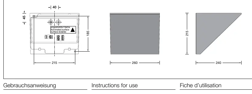
Installation
Preparation: Ensure the power is disconnected before starting. Use the provided hexagon socket head screws (wrench size 3 mm) to open the luminaire housing.
Mounting: Fix the luminaire base to the mounting surface using the provided elongated fixing holes. Ensure the correct orientation towards the area to be illuminated.
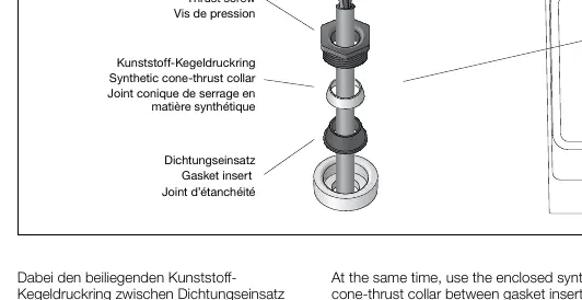
Cable Entry: The luminaire is equipped with two screw cable glands for through-wiring. The black gasket insert is for cables with a diameter of less than 10 mm. For cables with a diameter of 10-12 mm, use the enclosed grey gasket insert.
Assembly: When assembling the cable gland, use the enclosed synthetic cone-thrust collar between the gasket insert and the thrust screw (wrench size 22 mm). Tighten the cable gland firmly.
Electrical Connection
Connect the earth conductor and the power supply. For digital control, use the terminals marked DA, DA. If these terminals are not used, the luminaire will operate at full light output.
Maintenance and Care
Desiccant Pouch: To ensure maximum service life of electrical components, the enclosed desiccant pouch must be placed inside the luminaire at the position marked by the red information label immediately before closing the luminaire.
Cleaning: Clean the luminaire regularly with solvent-free cleansers. Do not use high-pressure cleaners.
LED Module Replacement: The LED module can be replaced by qualified persons using standard tools. Ensure the system is disconnected from power before opening.
Manufacturer information
BEGA
Practical help
Common problems
Luminaire not working or not controllable
Check the electrical connection and ensure the DALI terminals (DA, DA) are correctly connected if digital control is required.
Cable gland not sealing properly
Ensure the correct gasket insert is used (black for <10mm, grey for 10-12mm) and that the synthetic cone-thrust collar is placed between the gasket and the thrust screw.
Before use
- Ensure installation is performed by a qualified electrician.
- Verify the mounting surface is suitable for the luminaire.
- Check that the power cable diameter is between 7-12 mm.
- Ensure the desiccant pouch is placed inside the luminaire before final closure.
- Verify the gasket is positioned correctly.
Show more Show less
Specs in practice
- Safety Class I
- Requires an earth connection.
Images and diagrams
- The diagram on page 3 illustrates the correct assembly of the cable gland, showing the order of the thrust screw, cone-thrust collar, and gasket insert.
Model compatibility
- Compatible with DALI control systems.
- Suitable for through-wiring power cables with a diameter of 7-12 mm.

Manual page author
David Miller
Documentation analyst