Lighting / Emergency Lighting
Installation and User Guide for Bell Lighting 09012V2 LED Exit Sign
Quick guide for the Bell Lighting 09012V2 LED Exit Sign. Includes installation steps, wiring diagrams, maintenance schedules, testing procedures, and fault-finding indicators.
Table of contents
Manual images
Click an image to enlargeQuick guide from the manual
This emergency exit sign must be installed by a qualified electrician in accordance with current IEE wiring regulations BS7671:2018 and local building control. All testing must be carried out in accordance with EN 50172:2004. Ensure the ambient temperature does not exceed 30°C and there is adequate air ventilation around the fitting.
Product description
The Bell Lighting 09012V2 is an emergency LED exit blade with a viewing distance of 28m. It features a LiFePO4 3.2V 1500mAh battery with a 24-hour recharge time and 180-minute emergency duration.
Installation


- Remove the cover on the base. On the hanging range, the cover is held on by screws. The wall-mounted unit cover is held on by 4 recessed lugs.
- Fix the base to the wall or ceiling using an appropriate fixing method.
- Isolate the A.C. supply and connect the unit. An unswitched 240V A.C. supply must be connected.
- Fit the battery plug onto the two protruding metal pins on the edge of the PCB. Then, replace and secure the cover.
- On hanging signs, the length of the hanging wire can be adjusted by pushing the inner sleeve upwards. Excess wire can be cut and re-terminated into the PCB terminals.
- Perform an operational check by restoring the A.C. supply for 30 minutes, then isolate. The LEDs should illuminate for at least 10 seconds.
- Restore the A.C. supply and check that the charge indicator LED is 'on'.
Operation modes
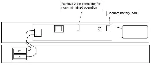
The unit is normally operated in the maintained mode. For non-maintained operation, remove the 2-pin connector from the PCB (refer to the wiring diagram). The battery is on automatic charge when the supply is connected.
Testing and maintenance
Routine Test Procedure:
- Once a day: Visual inspection of battery charge LED.
- Once a month: Simulate a mains failure to ensure the emergency mode functions correctly.
- Once each year: Place into emergency mode and check that the duration provided by the battery meets the specified time period.
Troubleshooting and fault finding
If the monitoring LED is not illuminated, check that the A.C. supply is healthy and the battery is connected. If the unit does not meet the required emergency period, discharge the battery and recharge for 24 hours. If the duration is still not achieved, the battery may need replacing.
Manufacturer information
BELL Lighting
Practical help
Common problems
LED not illuminated
Check that the A.C. supply is healthy and the battery lead is connected to the PCB.
Emergency duration not met
Discharge the battery and recharge for 24 hours. If the issue persists, the battery may need replacement.
Before use
- Ensure installation is performed by a qualified electrician.
- Verify A.C. supply is isolated before starting.
- Check that the battery lead is connected to the PCB.
- Set the switch position on the PCB before installation.
- Ensure ambient temperature does not exceed 30°C.
Specs in practice
- Operating temp: 0 to +40°C
- The allowed ambient temperature range for the device to function correctly.
- Battery: LiFePO4 3.2V 1500mAh
- The internal backup power source for emergency operation.
- Viewing Distance: 28m
- The maximum distance from which the exit sign is clearly visible.
Images and diagrams
- The wiring diagram illustrates the 2-pin connector for non-maintained operation and the battery lead connection point.
- The adjustment diagram shows how to push the inner sleeve upwards to adjust the hanging wire length.
Model compatibility
- Complies with current IEE wiring regulations BS7671:2018.
- Tests must be carried out in accordance with EN 50172:2004.

Manual page author
Emily Carter
User documentation editor
Prepares concise manual descriptions and highlights the most useful setup, operation, and maintenance information for readers.