Lighting / Emergency Lighting
User Manual for BELL Lighting 09066V2 Spectrum Emergency 6 in 1 Exit Blade
Quick guide for the BELL Lighting 09066V2 Spectrum Emergency 6 in 1 Exit Blade. Includes installation steps for recess, ceiling, and suspension mounting, wiring instructions, test modes, and LED status troubleshooting.
Table of contents
Manual images
Click an image to enlargeQuick guide from the manual
This equipment must be installed by a competent electrician in accordance with current IEE wiring regulations BS7671:2018 and local building control. Always switch off the mains supply before installation. Ensure adequate free air ventilation around the fitting and that the ambient room temperature does not exceed 35°C. The light source is not replaceable; the entire luminaire must be replaced at the end of its life.
Specifications
- Supply Voltage: 220-240VAC 50/60Hz
- Ambient Temperature: 0 to 35°C
- Insulation Class: II
- Ingress Protection: IP20
- Emergency Duration: More than 3 hours
- Battery: LiFePO4 3.2V 600mAh
- Recharge Time: 24 hours
- Visual Distance: 25m
- Operation: Maintained or Non-maintained
Installation
General Wiring:

- Ensure the AC supply is switched off.
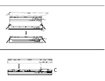
- Separate the base from the LED head.
- Insert AC supply wires into the connector.
- Insert the plug with the AC supply wires into the socket on the LED head.
- Insert the battery, ensuring correct polarity.
- For Maintained operation, connect the shorting plug to the CN2 connector. For Non-maintained operation, remove the shorting plug.
Mounting Methods:
- Recess Mounted: Connect the AC supply, push the base and LED head together, clip into the recess unit, and push the recess unit clips upwards into the ceiling (hole size 282x32mm).
- Ceiling Mounted: Affix the base to the ceiling using provided wall plugs and screws. Connect the AC supply and push the LED head into the base.
- Suspension Mounted: Slide suspension cables into the base, affix cables to the ceiling, connect the AC supply, and push the LED head into the base.
- Perpendicular/Parallel/Wall Mounted: Slide the triangular wall mount(s) onto the base, affix to the wall using provided hardware, connect the AC supply, and push the LED head into the base.
- Light Guide Mounting: Slide the light guide plate into the LED head, remove the protective film from the PET directional film, and adhere the film onto the light guide plate.
Operation and Testing
Test Switch Functionality:
- Short press (1s): Starts a 5-second function test.
- Hold (>10s): Resets the timer (System reset).
Modes:
- Self-test (ST): Push the dial switch to the left. Performs a 5-second functional test every 7 days and a 3-hour duration test 24 hours after installation, then every 180-182 days.
- Basic/Manual (BS): Push the dial switch to the right.
Important: Always select the desired test mode before applying power. Do not switch test mode while the luminaire is powered.
Troubleshooting and LED Status
The bi-colour indicator LED shows the system status:
- Permanent Green: Standby, System OK (Mains operation, battery charged).
- Fast flashing Green: Function test underway.
- Slow flashing Green: Duration test underway.
- Permanent Red: Lamp failure (Open Circuit, Short circuit, or LED failure).
- Fast flashing Red: Battery capacity failure (Battery failed duration test).
- Slow flashing Red: Battery fault (Incorrect voltage, Short circuit, or Open Circuit).
- Green and Red off: Battery Operation (Mains disconnected or Mains failure).
If an error is detected, the indicator switches to RED. After correcting the error and re-connecting the battery with mains disconnected, the indicator will switch back to GREEN when mains power is re-applied.
Manufacturer information
BELL Lighting
Practical help
Common problems
Indicator is Permanent Red
Indicates lamp failure (Open Circuit, Short circuit, or LED failure).
Indicator is Fast flashing Red
Indicates battery capacity failure; the battery failed the duration test.
Indicator is Slow flashing Red
Indicates battery fault (Incorrect battery voltage, Short circuit, or Open Circuit).
Indicator is Green and Red off
Indicates Battery Operation mode; mains is disconnected or there is a mains failure.
Before use
- Ensure AC supply is switched off before installation.
- Verify ambient room temperature does not exceed 35°C.
- Ensure adequate free air ventilation around the fitting.
- Select the desired test mode (ST/BS) using the dial switch before applying power.
- Ensure the battery is inserted with correct polarity.
- For Maintained operation, ensure the shorting plug is connected to the CN2 connector.
Specs in practice
- LiFePO4 3.2V 600mAh
- The type and capacity of the installed emergency battery.
- Deep Discharge Protection (DDP)
- Protects the battery from damage caused by excessive discharge during emergency operation.
- Maintained Operation
- The emergency light is on whenever the mains power is on, and switches to battery power during a failure.
Images and diagrams
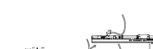
- Wiring: Connect AC supply wires to the connector and plug into the LED head socket.
- Dial Switch: Located on the unit to toggle between Self-test (ST) and Basic (BS) modes.
- CN2 Connector: Used for the shorting plug to enable Maintained operation.
Model compatibility
- Must be installed by a competent electrician.
- Light source is not replaceable; replace the whole luminaire at end of life.
- If Self-test mode is selected, additional manual tests are not required.

Manual page author
Emily Carter
User documentation editor
Prepares concise manual descriptions and highlights the most useful setup, operation, and maintenance information for readers.